Cars Config Guidelines – Arma 3
Additional functionality compared to A2/OA
- PhysX 3 integration
- IK for hands/legs
- Picture in Picture - Render to texture
- Random visual variants (textures, accessories, doors)
- Floating and sinking
- Reflectors, markerlights and beacons
Model requirements {p3d}
- A new PhysX lod
- There needs to be a lod (4e13) consisting of convex components as simple as possible, some 60 faces shall be sufficient for most cars
- Current public Oxygen version doesn't support showing correct name of this lod and displays only Geometry instead. Don't be afraid of having two geometries, it is going to be fixed with new tools.
- Just the main body of car should be in this lod, wheels are added by engine later
- There needs to be a lod (4e13) consisting of convex components as simple as possible, some 60 faces shall be sufficient for most cars
- Memory lod
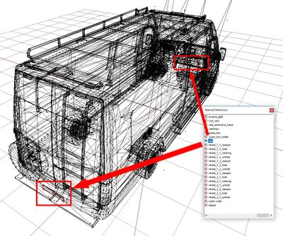
- There should be an axis for each wheel named wheel_X_Y_axis (X is position of wheel from front, Y is 1 for left and 2 for right), the name is defined in selected wheel as center
- There should be a point at the edge of each wheel named wheel_X_Y_bound which is used to determine wheel radius (distance from wheel axis is used for this) - there is no other need than placing the point at the edge, even memory points for tracks could be used for this, the name is defined in selected wheel as boundary
- Mirrors and screens should have their camera position defined in pipX_pos and direction in pipX_dir - parameters pointPosition and pointDirection in class RenderTargets
- Reflectors should have their position defined in LightCarHeadYXX (Y is a side - R/L, XX is a number) and direction defined in LightCarHeadYXX_end
- Mirrors and screens should have RTT texture: #(argb,256,512,1)r2t(rendertargetX,1.0) - where X in rendertarget should be a number corresponding to the renderTarget memory point.
- Mirrors and screens UV mapping should be increased to cover the entire UV map. This increases the "aperture" size of the mirror image.
- Randomly generated accessories should have their selections independent on all other selections (mainly the main body and all the glass selections), glass as a part of hide-able accessory should be handled as two separate selections
- Beacons and markerlights should have their material set to emit light
- Spare wheel should have defined selections for it, texture underneath and correct hitpoints like a normal wheel
- Man-held turrets shouldn't be hidden when destroying them without destroying the whole vehicle - IK issues would crash the game


Model config changes {model.cfg}
- Only the dampers are affected by the changes, best way to set them is to place an axis with the length of moveable part alongside the damper and set offsets to +-0.5
- Example:
{model.cfg}
class Wheel_1_1_Damper
{
	type = "translation";
	source = "damper";
	selection = "wheel_1_1_damper_land";
	axis = "posun wheel_1_1";
	animPeriod = 1;
	minValue = "0";
	maxValue = "1";
	offset0 = "0.5";
	offset1 = "-0.5";
	memory = 1;
};
- Sections for hiddenSelections[] should be set in model.cfg
New config parameters {config.cpp}
Basic parameters
Following parameters are defined in vehicle class.
- <Description>: Defines simulation type of the vehicle. PhysX simulation ends with letter "x", "carx", "tankx" ...
- <Type>: string
- <Default>: (required)
- simulation = "carx";
- <Description>: Defines how much dampers react to random little bumps on surface. It's only visual effect, doesn't influence drive simulation, only taken into account when calculating damper animation.
- <Type>: float
- <Default>: 0.0
- dampersBumpCoef = 0.3;
Differential parameters
Make sure you use values in the specified range to prevent PhysX errors
- <Description>: A number of differential types are supported: 4-wheel drive with open differential, 4-wheel drive with limited slip, front-wheel drive with open differential, front-wheel drive with limited slip, rear-wheel drive with open differential, rear-wheel drive with limited slip.
- <Type>: string; accepable values: "all_open", "all_limited", "front_open", "front_limited", "rear_open", "rear_limited"
- <Default>: "all_limited"
- differentialType = "all_limited";
- <Description>: If a 4-wheel drive differential is chosen (open or limited slip) this option allows the drive torque to be split unevenly between the front and rear wheels. Choosing a value of 0.5 delivers an equal split of the torque between the front and rear wheels; that is, the total torque delivered to the front wheels is equal to the total torque delivered to the rear wheels. Choosing a value greater than 0.5 delivers more torque to the front wheels, while choosing a value less than 0.5 delivers more torque to the rear wheels. This value is ignored for front-wheel drive and rear-wheel drive differentials.
- <Type>: float
- <Range>: (0,1)
- <Default>: 0.5
- frontRearSplit = 0.5
- <Description>: Limited slip differentials work by only allowing a certain difference in wheel rotation speed to accumulate. This prevents the situation where one wheel is slipping but ends up taking all the available power. Further, by allowing a small difference in wheel rotation speed to accumulate it is possible for the vehicle to easily corner by permitting the outside wheel to rotate quicker than the inside wheel.
This parameter describes the maximum difference in wheel rotation speed that is allowed to accumulate. The front bias is the maximum of the two front-wheel rotation speeds divided by the minimum of the two front-wheel rotation speeds. When this ratio exceeds the value of the front bias the differential diverts torque from the faster wheel to the slower wheel in an attempt to preserve the maximum allowed wheel rotation speed ratio.
This value is ignored except for front-wheel drive or four wheel drive with limited slip.
A good starting value is around 1.3. - <Type>: float
- <Range>: >= 1.0
- <Default>: 1.3
- frontBias = 1.3;
- <Description>: This is similar to frontBias except that it refers to the rear wheels.
This value is ignored except for rear-wheel drive or four wheel drive with limited slip.
A good starting value is around 1.3. - <Type>: float
- <Range>: >= 1.0
- <Default>: 1.3
- rearBias = 1.3
- <Description>: This value is similar to the frontBias and rearBias, except that it refers to the sum of the front wheel rotation speeds and the sum of the rear wheel rotation speeds.
This value is ignored except for four wheel drive with limited slip.
A good starting value is around 1.3.
- <Type>: float
- <Range>: >= 1.0
- <Default>: 1.3
- centreBias = 1.3
- <Description>: This describes how strongly the clutch couples the engine to the wheels and how quickly differences in speed are eliminated by distributing torque to the engine and wheels.
Weaker values will result in more clutch slip, especially after changing gear or stamping on the accelerator. Stronger values will result in reduced clutch slip, and more engine torque delivered to the wheels.
This value is to be edited only for very fine tweaking of the vehicle. Some clutch slip can be attributed to the numerical issues in the simulation at large timesteps, while some is a natural consequence of driving the car in an overly aggressive manner. A value of 10 is a good starting point. - <Type>: float
- <Range>: >= 0
- <Default>: 10.0
- clutchStrength = 10.0;
- <Description>: Value of minimal gear effectivity to hold current gear. If there is better gear and effectivity is below this value then change gear.
- <Type>: Array[i] where i = number of gears
- <Range>: (0,1)
- <Default>: 0.95 for every value (Neutral = 0.15 Not sure how important this is but we want to kick out of neutral very quickly)
- changeGearMinEffectivity[] = {0.95, 0.15, 0.95, 0.95, 0.95, 0.95, 0.95};
- <Description>: The switch time describes how long it takes (in seconds) for a gear change to be completed. It is impossible to change gear immediately in a real car. Manual gears, for example, require neutral to be engaged for a short time before engaging the desired target gear. While the gear change is being completed the car will be in neutral. A good trick might be to penalise players that use an automatic gear box by increasing the gear switch time.
- <Type>: float
- <Range>: >= 0
- <Default>: 0.01
- switchTime = 0.31;
- <Description>: Set the latency time of the autobox, specified in seconds.
Latency time is the minimum time that must pass between each gear change that is initiated by the autobox. - <Type>: float
- <Default>: 2.0
- latency = 1.0;
Engine parameters
- <Description>: Power of the engine in kW.
- <Type>: float
- <Default>: (required)
- enginePower = 600;
- <Description>: This is the maximum rotational speed of the engine expressed in radians per second. It could be calculated from maximum engine RPM like this:
maxOmega = (maxRpm*2*Pi)/60
- <Type>: float
- <Range>: > 0
- <Default>: 600 which is cca 6000 rounds per minute.
- maxOmega = 600;
- <Description>: This is the maximum torque that is ever available from the engine. This is expressed in Newton metres.
A starting value might be around 600.
- <Type>: float
- <Range>: > 0
- <Default>: value calculated from enginePower according to http://en.wikipedia.org/wiki/Horsepower#Relationship_with_torque
- peakTorque = 600;
- <Description>: These three values are used to compute the damping rate that is applied to the engine. If the clutch is engaged then the damping rate is an interpolation between dampingRateFullThrottle and dampingRateZeroThrottleClutchEngaged, where the interpolation is governed by the acceleration control value generated by the gamepad or keyboard. At full throttle dampingRateFullThrottle is applied, while dampingRateZeroThrottleClutchEngaged is applied at zero throttle. In neutral gear the damping rate is an interpolation between dampingRateFullThrottle and dampingRateZeroThrottleClutchDisengaged.
The three values allow a range of effects to be generated: good acceleration that isn't hampered by strong damping forces, tunable damping forces when temporarily in neutral gear during a gear change, and strong damping forces that will bring the vehicle quickly to rest when it is no longer being driven by the player.
Typical values in range (0.25,3). The simulation can become unstable with damping rates of 0. - <Type>: float, float, float
- <Range>: > 0 for each
- <Default>: 0.08, 2.0, 0.35
- dampingRateFullThrottle = 0.08;
- dampingRateZeroThrottleClutchEngaged = 2.0;
- dampingRateZeroThrottleClutchDisengaged = 0.35;
- <Description>: This is a graph of peak torque versus engine rotational speed. Cars typically have a range of engine speeds that produce good drive torques, and other ranges of engine speed that produce poor torques. A skilled driver will make good use of the gears to ensure that the car remains in the "good" range where the engine is most responsive. Tuning this graph can have profound effects on gameplay.
The x-axis of the curve is the normalised engine speed; that is, the engine speed divided by the maximum engine speed. The y-axis of the curve is a multiplier in range (0,1) that is used to scale the peak torque. The samples do not have to be equally spaced apart. You can distribute the points between both 0% rpm and 100% rpm points as you wish. - <Type>: Array[i][2] where i = number of samples, maximum 8;
- <Default>: {{0.0, 0.8}, {0.33, 1.0}, {1.0, 0.8}}
- torqueCurve[] = {{0.0, 0.8}, {0.33, 1.0}, {1.0, 0.8}};
Note: you can also use math in this definition, here is the same example from above using this technique:
- torqueCurve[] = {{"0/2400", "80/100"}, {"792/2400", "100/100"}, {"2400/2400", "80/100"}};
Wheel parameters
This parameters relates to each wheel. In the vehicle class, there has to be subclass called Wheels, which contains subclass for every wheel the vehicle has. These are the parameters that could be defined in that subclasses.
General parameters
- <Description>: Name of the bone, used for wheel and suspension animations. The standard bone structure would be as such: damperbone-> steeringbone->rotatingbone (example: wheel_1_1_damper-> wheel_1_1_steering -> wheel_1_1) . As boneName you would set the rotatingbone (e.g. wheel_1_1). In the visual LODs this "rotatingbone" is generally the selection of the tire.
- <Type>: string
- <Default>: ""
- boneName = "wheel_1_1";
- <Description>: If true, wheel is steerable, false - wheel is fixed.
- <Type>: bool
- <Default>: (required)
- steering = true;
- <Description>: Defines if wheel is on the right or left side of the vehicle
- <Type>: string
- <Default>: "right"
- side = "left";
Wheel PX parameters
- <Description>: Center of the wheel (axis)
- <Type>: memory point
- <Default>: (required)
- center = "wheel_1_1_axis";
- <Description>: Point on the outside rim of the tire, used to calculate radius of the wheel (distance between center and boundary).
- <Type>: memory point
- <Default>: (required)
- boundary = "wheel_1_1_bound";
- <Description>: Has no use right now. This is the full width of the wheel in metres. This parameter has no bearing on the handling.
- <Type>: float
- <Range>: > 0
- <Default>: 0.3*(raidus of the wheel)
- width = "0.2";
- <Description>: This is the combined mass of the wheel and the tire in kg. Typically, a wheel has mass between 20Kg and 80Kg but can be lower and higher depending on the vehicle.
- <Type>: float
- <Range>: > 0
- <Default>: 10.0
- mass = 150;
- <Description>: This is the component of the wheel's moment of inertia about the rolling axis. Larger values make it harder for the wheel to rotate about this axis, while easier values make it easier for the wheel to rotate about the rolling axis. Another way of expressing this is that a high MOI will result in less wheel spin when stamping on the accelerator because it is harder to make the wheel spin. Conversely, lower values of MOI will result in more wheel spin when stamping on the accelerator.
If the wheel is approximately cylindrical then a simple formula can be used to compute MOI:MOI = 0.5 * Mass * Radius * Radius
There is no reason, however, to rely on equations to compute this value. A good strategy for tuning this number might to be start with the equation above and then make small tweaks to the value until the handling is as desired. - <Type>: float
- <Range>: > 0
- <Default>: 0.5 * WheelMass * WheelRadius * WheelRadius
- MOI = 40;
- <Description>: This value describes how quickly a freely spinning wheel will come to rest. The damping rate describes the rate at which a freely spinning wheel loses rotational speed. Here, a freely spinning wheel is one that experiences no forces except for the damping forces arising from the wheel's internal bearings. Higher damping rates result in the wheel coming to rest in shorter times, while lower damping rates result in the wheel maintaining speed for longer. Values in range (0.25, 2) seem like sensible values. Experimentation is always a good idea, even outside this range. Always exercise some caution with very small damping rates. In particular, a damping rate of exactly 0 should be avoided.
- <Type>: float
- <Default>: 0.1
- dampingRate = 0.1;
- dampingRateDamaged = 1.0;
- dampingRateDestroyed = 1000.0;
- <Description>: This is the value of the torque applied to the wheel when the brakes are maximally applied. Higher torques will lock the wheel quicker when braking, while lower torques will take longer to lock the wheel. This value is strongly related to the wheel MOI because the MOI determines how quickly the wheel will react to applied torques.
A value of around 1500 is a good starting point for a vanilla wheel but a google search will reveal typical braking torques. One difficulty is that these are often expressed by manufacturers as braking horsepower or in "pounds inches". The values required here are in "Newton metres". - <Type>: float
- <Range>: >= 0
- <Default>: 2500
- maxBrakeTorque = 7500;
- <Description>: This is the same as the max brake torque except for the handbrake rather than the brake. Typically, for a 4-wheeled car, the handbrake is stronger than the brake and is only applied to the rear wheels. A value of 4000 for the rear wheels is a good starting point, while a value of 0 is necessary for the front wheels to make sure they do not react to the handbrake.
- <Type>: float
- <Range>: >= 0
- <Default>: 2*maxBrakeTorque
- maxHandBrakeTorque = 0
Wheel simulation parameters
- <Description>: This is the direction of the suspension in the downward direction in the rest configuration of the vehicle. A vector that
points straight downwards is a good starting point.
- <Type>: Array[3]
- <Default>: { 0, -1, 0 }
- suspTravelDirection[] = { 0, -1, 0 };
- <Description>: This is the application point of the suspension force.
In a real vehicle the suspension forces are mediated through the suspension strut. These are often incredibly complex mechanical systems that are computationally expensive to simulate. As a consequence, instead of modelling the details of the suspension strut, it makes sense to assume that the suspension strut has an effective point at which it applies the force to the rigid body. Choosing that point, however, needs careful consideration. At the same time, it opens up all sorts of tweaking possibilities, freed from the constraints of the real world.
Deciding on the suspension force application point requires some thought. The suspension is very close to the wheel so the wheel center is a good starting point. Consider a line through the wheel center and along the suspension travel direction. Somewhere along this line seems like an even better idea for the application point, albeit not completely scientific. For a standard 4-wheeled car it makes sense that the application point is somewhere above the wheel center but below the centre of mass of the rigid body. It is probably above the wheel centre because the suspension is mostly above this point. It can be assumed that it is somewhere below the rigid body centre of mass because otherwise vehicles would lean out of the turn rather than in to the turn. This narrows down the application point to really quite a small section of a known line.
When editing the suspension force application point it is important to bear in mind that lowering the app point too far will result in cars leaning more into the turn. This can have a negative effect on handling because the inner wheel can take so much load that the response saturates, while the outer wheel ends up with reduced load and reduced turning force. The result is poor cornering. Conversely, setting the app point too high will result in cornering that looks unnatural. The aim is to achieve a good balance. - <Type>: memory point
- <Default>: center
- suspForceAppPointOffset = "wheel_1_1_axis";
- <Description>: This is almost the same as the suspension force app point except for the lateral and longitudinal forces that develop on the tire.
A good starting point is to duplicate the suspension force application point. Only for really detailed editing is it advised to start tweaking the tire force app offset independently of the suspension force app offset. - <Type>: memory point
- <Default>: suspForceAppPointOffset
- tireForceAppPointOffset = "wheel_1_1_axis";
Suspension parameters
- <Description>: These values describe the maximum compression and elongation in metres that the spring can support. The total travel distance along the spring direction that is allowed is the sum of maxCompression and maxDroop.
A simple way to illustrate the maximum droop and compression values is to consider a car that is suspended in mid-air so that none of the wheels are touching the ground. The wheels will naturally fall downwards from their rest position until the maximum droop is reached. The spring cannot be elongated beyond this point. Now consider that the wheel is pushed upwards, first to its rest position, then further pushed until the spring can no longer be compressed. The displacement from the rest position is the maximum compression of the spring.
It is important to choose the maximum compression value so that the wheel is never placed where the visual mesh of the wheel intersects the visual meshes of the car chassis. Ideally, these values will be exported from the 3D modeller. - <Type>: float
- <Range>: >= 0 Important: If one of the values is zero, the other must be greater than zero
- <Default>: 0.15
- maxCompression = 0.15;
- maxDroop = 0.15;
- <Description>: This is the mass in kg that is supported by the suspension spring.
A vehicle with rigid body centre of mass at the centre of the four wheels would typically be equally supported by each of the suspension springs; that is, each suspension spring supports 1/4 of the total vehicle mass. If the centre of mass was moved forward then it would be expected that the front wheels would need to support more mass than the rear wheels. Conversely, a centre of mass nearer the rear wheels ought to result in the rear suspension springs supporting more mass than at the front. All the mass of the vehicle must be "carried" by the sprung mass values, means: The sum of sprungMass values for all Wheels must be equal to the vehicle's weight. - <Type>: float
- <Range>: > 0
- <Default>: vehicleMass/numberOfWheels
- sprungMass = 2066;
- <Description>: This is the strength of the suspension spring in Newtons per metre. The spring strength has a profound influence on handling by modulating the time it takes for the vehicle to respond to bumps in the road and on the amount of load experienced by the tire.
Key to the understanding the effect of spring strength is the concept of a spring's natural frequency. Consider a simple spring system, such as a pendulum swinging back and forth. The number of trips per second that the pendulum makes from full left to full right and then back again is called the natural frequency of the pendulum. A more powerful pendulum spring will result in the pendulum swinging faster, thereby increasing the natural frequency. Conversely, increasing the pendulum mass will result in a slower oscillation, thereby reducing the natural frequency.
In the context of a suspension spring supporting a fixed portion of vehicle mass, the strength of the spring will affect the natural frequency; that is, the rate at which the spring can respond to changes in load distribution. Consider a car taking a corner. As the car corners it leans in to the turn, putting more weight on the suspensions on the outside of the turn. The speed at which the spring reacts by applying forces to redistribute the load is controlled by the natural frequency. Very high natural frequencies, such as those on a racing car, will naturally produce twitchy handling because the load on the tires, and therefore the forces they can generate, is varying very rapidly. Very low natural frequencies, on the other hand, will result in the car taking a long time to straighten up even after the turn is complete. This will produce sluggish and unresponsive handling.
Another effect of strength and and natural frequency is the response of a car to a bump in the road. High natural frequencies can result in the car responding very strongly and quickly to the bump, with the wheel possibly even leaving the road for a short while. This not only creates a bumpy ride but also periods of time when the tire is generating no forces. Weaker springs will result in a smoother trip over the bump, with weaker but more constant tire forces. A balance must be found to tune the car for the expected types of turn and terrain.
The natural frequency of the spring presents a challenge for computer simulation. A smooth and stable simulation requires that the spring is updated at a frequency much greater than the spring's natural frequency. An alternative way of expressing this is to consider the period of the spring relative to the timestep of the simulation. The period of the spring is the time the spring takes to complete a single oscillation, and is mathematically equal to the reciprocal of the natural frequency. In order to achieve a stable simulation the spring must be sampled at several points during each oscillation. A natural consequence of this observation is that the simulation timestep must be significantly smaller than the period of the spring. To discuss this further it is helpful to introduce a ratio that describes the number of simulation updates that will occur during each spring oscillation. This ratio is simply the spring period divided by the timestepalpha = sqrt(mSprungMass / mSpringStrength) / timestep
wheresqrt(mSprungMass / mSpringStrength)is the period of the spring. An alpha value of 1.0 means that the chosen timestep and spring properties only allow a single sample of the spring during each oscillation. As described above, this is almost guaranteed to produce unstable behaviour. In fact, the argument presented so far suggests a value of alpha signifcantly greater than 1.0 is essential to produce a smooth simulation. The exact value of alpha at which stability emerges is very difficult to predict and depends on many other parameters. As a guide, however, it is recommended that the timestep and spring properties are chosen so that they produce an alpha value greater than 5.0; that is, a minimum of five simulation updates per spring cycle.
When tuning a suspension spring it can be very useful to use manafacturer data to discover typical values used across a range of vehicle types. This data is not always readily available. An alternative strategy would be to think in terms of the natural frequency of the spring by imagining how quickly the car would oscillate up and down if it was dropped onto the ground from a height of, say, 0.5m. The springs of a typical family car have natural frequency somewhere between 5 and 10; that is, such a car would make 5-10 oscillations per second if gently dropped to the ground. If the mass supported by the spring is already known then the spring strength can be calculated from the following equationspringStrength = naturalFrequency * naturalFrequency * sprungMass
- <Type>: float
- <Range>: > 0
- <Default>: sprungMass*5,0*5,0
- springStrength = 51653;
- <Description>: This describes the rate at which the spring dissipates the energy stored in the spring.
Key to the understanding of damper rate are the concepts of under-damping, over-damping, and critical damping. An over-damped pendulum displaced from rest is unable to make a single back-and-forth trip before it dissipates all its energy, while an under-damped pendulum would be able to make at least a single back-and-forth trip. A critically damped pendulum makes exactly a single back-and-forth trip before expending all its energy.
For vehicle suspension springs, it is tpically important to make sure that the spring has a damper rate that produces over-damping but not by too much. When cornering, for example, it is important that the spring doesn't over-respond by shifting the weight from the left suspension to the right suspension then back again. If this happened the tire load, and the forces generated, would be extremely variable, resulting in twitchy and uncontrollable handling. A very heavily over-damped spring, on the other hand, will feel sluggish and unresponsive. The concept of critical damping can be used to help tune the damping rate of the spring. It is helpful to introduce a value known as the damping ratio, which helps to mathematically describe the under-damping, critical damping and over-damping regimes.dampingRatio = springDamperRate / (2 * sqrt(springStrength * sprungMass))
A dampingRatio with value greater than 1.0 produces over-damping, a value of exactly 1.0 generates critical damping, and a value less than 1.0 is under-damped. It can be useful to first think about whether the spring will be under-damped or over-damped, then think about how far it will be from critical damping. This process allows a number to be subjectively applied to the damping ratio. From here the damping rate can be directly computed by rearranging the equation abovespringDamperRate = dampingRatio * 2 * sqrt(springStrength * sprungMass)
A typical family car is probably slightly over-damped, having dampingRatio with value perhaps just over 1.0. A guideline would be that values very far from critical damping are likely to be unrealistic and will either produce sluggish or twitchy handling. It is difficult to put an exact figure on this but somewhere between 0.8 and 1.2 seems like a good starting point for the damping ratio. - <Type>: float
- <Range>: >= 0
- <Default>: 0,4*2*sqrt(springStrength*sprungMass)
- springDamperRate = 8264;
Tire parameters
- <Description>: The longitudinal tire force is approximately the product of the longitudinal stiffness per unit longitudinal slip (in radians) per unit gravity and the longitudinal slip and the magnitude of gravitational acceleration.
Increasing this value will result in the tire attempting to generate more longitudinal force when the tire is slipping. Typically, increasing longitudinal stiffness will help the car accelerate and brake. The total tire force available is limited by the load on the tire so be aware that increases in this value might have no effect or even come at the expense of reduced lateral force. - <Type>: float
- <Default>: 10000
- longitudinalStiffnessPerUnitGravity = 10000;
- <Description>: These values together describe the lateral stiffness per unit lateral slip (in radians) of the tire. The lateral stiffness of a tire has a role similar to the longitudinal stiffness, except that it governs the development of lateral tire forces, and is a function of tire load. Typically, increasing lateral stiffness will help the car turn more quickly. The total tire force available is limited by the load on the tire so be aware that increases in this value might have no effect or even come at the expense of reduced longitudinal force.
The combination of the two values latStiffX and latStiffY describe a graph of lateral stiffness as a function of normalised tire load.
Typical for car tires is a graph that has linear response close to zero load but saturates at greater loads. This means that at low tire loads the lateral stiffness has a linear response to load; that is, more load results in more stiffness. At higher tire loads the tire has a saturated response and is in a regime where applying more load will not result in more tire stiffness. In this latter regime it would be expected that the tire would start slipping.
The parameter latStiffX describes the normalised tire load above which the tire has a saturated response to tire load. The normalised tire load is simply the tire load divided by the load experienced when the vehicle is perfectly at rest. A value of 2 for latStiffX means that when the the tire has a load more than twice its rest load it can deliver no more lateral stiffness no matter how much extra load is applied to the tire. The parameter latStiffY describes the maximum stiffness per unit of lateral slip (in radians) per unit rest load. The maximum stiffness is delivered when the tire is in the saturated load regime, governed in turn by latStiffX.
A good starting value for latStiffX is somewhere between 2 and 3. A good starting value for latStiffY is around 18 or so. - <Type>: float, float
- <Default>: 25, 180
- latStiffX = 25;
- latStiffY = 180;
- <Description>: These six values describe a graph of friction as a function of longitudinal slip. Vehicle tires have a complicated response to longitudinal slip and this graph attempts to quickly describe this relationship.
Typically, tires have a linear response at small slips. This means that when the tire is only slightly slipping it is able to generate a response force that grows as the slip increases. At greater values of slip, the force can actually start to decrease from the peak value that occurs at the optimum slip. Beyond the optimum slip the tire eventually stops behaving less and less efficiently and hits a plateau of inefficiency.
The first two values describe the friction at zero tire slip: frictionVsSlipGraph[0][0] = 0, and frictionVsSlipGraph[0][1] = friction at zero slip.
The next two values describe the optimum slip and the friction at the optimum slip: frictionVsSlipGraph[1][0] = optimum slip, frictionVsSlipGraph[1][1] = friction at optimum slip.
The last two values describe the slip at which the plateau of inefficiency begins and the value of the friction available at the plateau of inefficiency: frictionVsSlipGraph[2][0] = slip at the start of the plateau of inefficiency, frictionVsSlipGraph[2][1] = the friction available at the plateau of inefficiency.
The friction values described here are used to scale the friction of the ground surface. This means they should be in range (0,1) but this is not a strict requirement. Typically, the friction from the graph would be close to 1.0 in order to provide a small correction to the ground surface friction.
A good starting point for this is a flat graph of friction vs slip with these values:frictionVsSlipGraph[0][0] = 0.0; frictionVsSlipGraph[0][1] = 1.0; frictionVsSlipGraph[1][0] = 0.5; frictionVsSlipGraph[1][1] = 1.0; frictionVsSlipGraph[2][0] = 1.0; frictionVsSlipGraph[2][1] = 1.0;
- <Type>: Array[3][2]
- <Default>: { { 0, 1 }, { 0.5, 1 }, { 1, 1} }
- frictionVsSlipGraph[] = { { 0, 1 }, { 0.5, 1 }, { 1, 1 } };
Floating and sinking
WaterLeakiness should be amount of water in liters that goes into selected object per second. This is set to zero by engine for all vehicles with simulation of a ship or having canFloat = 1 (unless they are toppled of destroyed, then config value takes precedence). WaterLeakiness = 10; seems to be a good value to start with for all kinds of vehicles no matter the size (which is a bit spooky, but it works).
PhysX 3 integration
WheelMask
- thrustDelay is time in second in which thrust goes from 0 to 1 when standing still (doesn't affect driving car during change of gears), 0.2 seems to be a reasonable value. You may want to tweak this to higher values if wheels slide during initial acceleration.
- brakeIdleSpeed is speed in m/s under which the brakes are automatically applied to the vehicle. This speed should be reasonably low, higher value would mean strange breaking of slow cars, too low value would cause inability to stop the car.
- idleRpm sets the idle RPM of engine. Primary use is for sound engine
- redRpm sets the maximum for engine RPM, should be according to maxOmega (see later)
Anti-roll bars
- Anti-roll bars is the system in vehicle that should prevent it to do a barrel-roll during sharper turns. Using ARB enables us to make center of mass realistically high and cause cars to roll down the steep slopes if placed sideways to the slope. It works the same way as the real ones - system computes difference of applied weight to wheels in pair and tries to compensate difference by applying opposite forces.
- antiRollbarForceCoef is a coefficient of applied force, could be taken as strength of the system. Setting this value to zero disables ARB (and all next values), which is good for civilian vehicles, higher values reduce not only the risk of rolling, but effects of suspension.
- antiRollbarForceLimit is the highest strength of ARB applied to vehicle. We may want to roll the car at certain situations (full van taking sharp hand-brake turn at high speed), tunning without diag mode is almost impossible because we are not able to imagine forces needed (values are rather low, 2 should be high enough for most of vehicles)
- antiRollbarSpeedMin and antiRollbarSpeedMax are limits of applied force coefficient. Coefficient is 0 at speeds lower than antiRollbarSpeedMin, interpolates to antiRollbarForceCoef at antiRollbarSpeedMax and is set to antiRollbarForceCoef for any higher speeds. This allows cars to drive on steep slopes using their radial speed, falling of the hill once they stop and rolling over at too high speeds (where coefficient doesn't grow and force is limited by the limit).
Complex gearbox
- All PhysX 3 vehicles use complex gearbox to give some data to PhysX gearbox
- Complex gearbox settings is inside class complexGearbox which is a subclass of vehicle class
- GearboxRatios[] is an array of gear names and gear ratios starting with reverse gear (with negative ratios), neutral gear (which should have zero ratio) and forward ratio (eg: {"R1",-3.231,"N",0,"D1",2.462,"D2",1.870,"D3",1.241,"D4",0.970,"D5",0.711};). Gear names are not used in retail version, they are just for epevehicle diagnostics. Important: There can only be one reverse Gear (which must have negative value) and one Neutral gear (which must have 0 as ratio). All forward gears must have a value greater than zero and they must be ordered from high ratio to low
- TransmissionRatios[] is an array of transmission ratios in the same format as gearboxRatios. Most of cars have only one transmission ratio, some heavy trucks may have two. The final ratio of engine is gearboxRatio * TransmissionRatio, that means transmissionRatios shouldn't be multiplicates of each other and gearbox ratios to prevent the same final ratio for two different gears.
- gearBoxMode is set to full-auto by engine. The full-auto mode can skip gears to get the best possible gear for each condition.
- moveOffGear defines what gear an automatic or semi-automatic gearbox will move off from stationary in. 1 by default.
- driveString, neutralString and reverseString define displayed strings for driving forward, neutral and backward.
{config.cpp}
class complexGearbox
{
	GearboxRatios[] = { "R1", -3.231, "N", 0, "D1", 2.462, "D2", 1.870, "D3", 1.241, "D4", 0.970, "D5", 0.711 };
	TransmissionRatios[] = { "High", 4.111 }; // Optional: defines transmission ratios (for example, High and Low range as commonly found in offroad vehicles)
	moveOffGear			= 1; // defines what gear an automatic or semi-automatic gearbox will move off from stationary in. 1 by default.
	driveString			= "D"; // string to display in the HUD for forward gears.
	neutralString		= "N"; // string to display in the HUD for neutral gear.
	reverseString		= "R"; // string to display in the HUD for reverse gears.
};
Gearbox parameters
- Some gearbox parameters are defined outside of class complexGearbox, they are mainly to setup automatic gearbox
- changeGearMinEffectivity[] Value of minimal gear effectivity to hold current gear. If there is better gear and effectivity is below this value then change gear. It is an array of effectivities ordered by gears in complex gearbox. Neutral should have rather low effectivity (0.15 seems to be a good value), drive gears should have rather high value (around 0.95) to prevent switching gears too often
- switchTime The switch time describes how long it takes (in seconds) for a gear change to be completed. RPM interpolate to optimal value for the new gear at current speed during the changing of gears. The time should be rather low, around 0.3 s, to keep the momentum of the car.
- latency is the minimum time (in seconds) that must pass between each gear change that is initiated by the autobox. This should be set to value higher than switchTime. Setting this time too low makes some issues with changing gears - the car slows down a lot
Different amount of torque
- coefficients for different speeds of Slow, Forward and Fast are now configurable
- slowSpeedForwardCoef is set to 0.3 by default
- normalSpeedForwardCoef is set to 0.85 by default
- default speed coefficient for fast movement is 1 meaning that full throttle is applied and maximal speed is maxSpeed of the vehicle (it is going to apply less throttle upon reaching the limit)
IK for hands and legs
- It's not Inverse Kinematics in fact, but as close to it as possible.
- A soldier should have IK defined for hands and legs by default
- Each vehicle pose using IK should have leftHandIKCurve[] and rightHandIKCurve[] set to 1
- Driver should have driverLeftHandAnimName and driverRightHandAnimName defined as drive wheel bone of the vehicle (drivewheel by default)
- Gunner should have gunnerLeftHandAnimName and gunnerRightHandAnimName defined on handles of the gun, or shaking bone of the weapon shall be sufficient (usually something like otocHlaven_shake)
- Double check names of bones if the game crashes upon loading this vehicle and call stack points to IK. Wrong definition causes CTD all the time and removing the bone causes the same (eg. by hiding it).
Picture in Picture for screens and mirrors
- All sources for textures to be rendered on are defined in class RenderTargets which is a subclass of vehicle class
- Each source is a separate subclass with unique name
- parameter renderTarget defines which texture shall the source be mapped at (only the rendertargetX part is used)
- class CameraView1 is a subclass of this source and contains all the parameters for rendered scene
- pointPosition and pointDirection should be respective memory points in model
- renderQuality is in range from 0 to 2 and defines quality of rendering for said source
- renderVisionMode defines the vision mode - 0 = HDR, 1 = NightVision, 2 = ThermalVision, 3 = Color, 4 = Mirror
- fov defines field of view of this source
- BBoxes defines bounding boxes for selected r2t texture. When selected bounding box is beyond player view, r2t source will be no longer rendered saving performance for other Picture in Picture windows. Bounding boxes doesn't need to be very precise - method to calculate their is not 100% accurate to maximize performance.
{config.cpp}
class RenderTargets
{
	class LeftMirror
	{
		renderTarget = "rendertarget0";

		class CameraView1
		{
			pointPosition		= "PIP0_pos";
			pointDirection		= "PIP0_dir";
			renderQuality 		= 2;
			renderVisionMode 	= 0;
			fov 				= 0.7;
		};

		BBoxes[]	= { "PIP0_TopLeft", "PIP0_TopRight", "PIP0_BottomLeft", "PIP0_BottomRight" };
	};
};
Random visual variants
- Randomisation of variants is done by script ran upon start of mission via init event handler
- The car should inherit class EventHandlers: EventHandlers
{config.cpp}
init event handler should be changed to something like this: init = "(_this select 0) execVM ""\pathToCar\scripts\scriptName.sqf"""; - Don't forget to hide all the added accessories upon destruction of vehicle, they are usually in proxies, this is handled by killed event handler:
{config.cpp}killed = "_this call (uiNamespace getVariable 'BIS_fnc_effectKilled'); _this select 0 animate [""RandomAnimation"", 0];
Random variants script
- All random settings should be done on server side to prevent different car looks for different users
- Y stands for the number of random variants
- Even all the animations should be handled server-side to ease clients, RandomAnimation shall be replaced by any animation needed to be randomly chosen, X stands for animation phase// {script.sqf} waitUntil { !(isNil { _this getVariable "BIS_randomSeed1" }) }; _randomSeed1 = _this getVariable "BIS_randomSeed1";
- Random textures shall be taken with this statement:// {script.sqf} _this setObjectTexture [0, ["\pathToCar\Data\variant_1_co.paa", /* ..., */ "\pathToCar\Data\variant_Y_co.paa"] select _randomSeed1];
Reflectors, markerlights and beacons
Reflectors
- Reflectors need to be defined in class Reflectors
- Default cars should have two reflectors defined as separate subclasses inside class Reflectors. These two classes should differ only in position, direction, hitpoint and selection. Position and direction are self-descriptive, they use memory points in mode, hitpoint is the name of selection in hitpoint lod in model, selection is a visual selection in resolution lods.
- Most of reflectors should have useFlare set to 1, they are bright enough to have a flare. Size of this flare is defined by flareSize, value should be rather low, around 0.1 seems to be good for start.
- class Attenuation inside each reflector subclass defines behavior of light from distance. Attenuation is combination of constant, linear and quadratic coefficient, start is a distance from position where attenuation starts to work (the light is at it is full strength if distance is lower than start).
- aggregateReflectors[] outside of Reflectors class is used to ease computing of too many light sources and combines light together. Both reflectors should be aggregated for a default car but feel free to experiment. Just run some FPS test after testing non-standard settings.
Markerlights
- Markerlights are purely model side based on assigned emissive materials
Beacons
- Beacons consist of two parts on model side - emissive one and unlit one. The emissive one is hidden by default by an user controller and periodically hidden by time controller in model.cfg
- Config contains only user actions to turn beacons off/on by hiding/unhiding them, this is inside class UserActions: UserActions
- There should be two actions per beacons set - one to turn them off and other to turn them on, each as a subclass of UserActions
{config.cpp}class UserActions : UserActions { class beacons_start { userActionID = 50; displayName = "Beacons start"; displayNameDefault = ""; position = "mph_axis"; radius = 1.8; animPeriod = 2; onlyForplayer = false; condition = "this animationPhase ""BeaconsStart"" < 0.5 && alive this && driver this == player"; statement = "this animate [""BeaconsStart"", 1];"; }; class beacons_stop : beacons_start { userActionID = 51; displayName = "Beacons stop"; condition = "this animationPhase ""BeaconsStart"" > 0.5 && alive this && driver this == player"; statement = "this animate [""BeaconsStart"", 0];"; }; };
- There should be two actions per beacons set - one to turn them off and other to turn them on, each as a subclass of UserActions
Steering properties for player
- Patch 1.50 brings a new class for setting handling properties for each vehicle class separately
- This affects only player, AI still uses steering based on their properties (turnCoef, steerAheadSimul, steerAheadPlan, predictTurnPlan, predictTurnSimul)
{config.cpp}
class myCar_F : Car_F
{
	class PlayerSteeringCoefficients // steering sensitivity configuration
	{
		turnIncreaseConst	= 0.3; // basic sensitivity value, higher value = faster steering
		turnIncreaseLinear	= 1.0; // higher value means less sensitive steering in higher speed, more sensitive in lower speeds
		turnIncreaseTime	= 1.0; // higher value means smoother steering around the center and more sensitive when the actual steering angle gets closer to the max. steering angle

		turnDecreaseConst	= 5.0; // basic caster effect value, higher value = the faster the wheels align in the direction of travel
		turnDecreaseLinear	= 3.0; // higher value means faster wheel re-centering in higher speed, slower in lower speeds
		turnDecreaseTime	= 0.0; // higher value means stronger caster effect at the max. steering angle and weaker once the wheels are closer to centered position

		maxTurnHundred		= 0.7; // coefficient of the maximum turning angle @ 100km/h; limit goes linearly to the default max. turn. angle @ 0km/h
	};
};
Firing from vehicles
- Patch 1.54 brings a new way to use firing from vehicle limits
- Previous definition of limits using limited field of view and dynamicViewLimits is still available
- There are several points common for both systems - they are set up in base class CargoTurret
- Important part is that despite being turrets, positions for FFV use standard Cargo proxies in model
- The most important property of cargo turrets is isPersonTurret which has the values in range from 0 to 2:
- 0 means turret is not usable for FFV
- 1 means turret is usable for FFV
- while 2 means that turret is usable for FFV both turned in and out
- CargoTurret usually contains property dontCreateAI = 1; to prevent automatic creation of AI soldiers for the turret
- Old way of defining view limits used standard turret properties (minElev, maxElev, minTurn, maxTurn) to describe a roughly rectangular area of view
- It is possible to use subclass dynamicViewLimits containing arrays for each other turrets. These arrays limit the initial view in case turret with their name is filled by a unit
- Limits actually used are minimal based on all the dynamic limits for said turret
- New (as for 1.54) system uses two curves to define upper and lower limits of view and is defined separately for turned-in and turned-out positions
- Additional properies allowLauncherIn and allowLauncherOut have been added to allow use of launchers in vehicle
- Subclasses TurnIn and TurnOut are used to define separate limits for turned-in and turned-out positions via a set of two arrays - limitsArrayTop[] and limitsArrayBottom[]
- Each of these arrays contains pairs of numbers which are vertical and horizontal angles of points on the curve - these points are then connected to create a polygon of view
- These new subclasses may be used even for standard turrets on vehicles
{config.cpp}
class CargoTurret;
class Turrets : Turrets
{
	class CargoTurret_01 : CargoTurret
	{
		gunnerAction = "passenger_flatground_3";
		memoryPointsGetInGunner = "pos cargo RR";
		memoryPointsGetInGunnerDir = "pos cargo RR dir";
		gunnerName = "$STR_A3_TURRETS_CARGOTURRET_R2";
		gunnerCompartments = "Compartment2";
		proxyIndex = 2;
		isPersonTurret = 2; // this turret is able to fire both when turned in and out

		// Old view limits inbounce

		maxElev = 45;	// vertical limit for field of view
		minElev = -5;	// vertical limit for field of view
		maxTurn = 95;	// horizontal limit for field of view
		minTurn = -95;	// horizontal limit for field of view
		class dynamicViewLimits	// additional limits according to filled positions
		{
			CargoTurret_02[] = { -65, 95 };	// if CargoTurret_02 is filled, this turret cannot turn that much to negative way (limits from -95 to -65 degrees)
		};

		// New view limits inbounce

		class TurnIn // limits for gunner turned in
		{
			limitsArrayTop[] = { { 33.8208, -93.9616 }, { 40.8906, 66.5705 } }; // points for the upper curve
			limitsArrayBottom[] = { { -9.4643, -94.5753 }, { -8.3683, -67.6867 }, { -9.7173, 43.6372 }, { -10.1082, 78.9166 } }; // points for the lower curve
		};

		class TurnOut : TurnIn {}; // turn out uses the same limits as turn in this time
	};

	class CargoTurret_02 : CargoTurret {...}; // there is some second turret just to show the class name for dynamic limits
};
Plate Numbers
- In order to use randomized plate numbers on your vehicle first, you need to ensure that you have proper section defined in CfgModels
- Default name of that selection is "spz", but it can be changed in PlateInfos class inside of your vehicle. With that selection properly defined in cfgModels, you can place a face in visual LOD, which will be used to generate square surface used by plate numbers
Configuration
- model.cfg
class CfgModels
{
	class YourVehicle
	{
		sections[] =
		{
			"spz"
		};
	};
};
- Model
- Root config
// Located in root config
fontPlate = "RobotoCondensed";
- CfgWorlds part
class CfgWorlds
{
	class YourWorld
	{
		// Located in map config (cfgWorlds)
		// if plateFont is not present then core one is used
		plateFont = "RobotoCondensed";
		// "#" represent number & "$" represents letter
		plateFormat = "ML$ - #####";
		// List of letter that can appear on plate number
		plateLetters = "ABCDEGHIKLMNOPRSTVXZ";
	};
};
- CfgVehicles part
In case you don't want to use island plate randomization because i.e. you are doing some military vehicle, you can override those settings inside PlateInfos classclass CfgVehicles { class YourVehicle { class PlateInfos { // name of section where plate number should generated name = "spz"; // color used for plate number in (r,g,b,a) format color[] = { 1.00, 0.00, 1.00, 1 }; plateFont = "RobotoCondensedLight"; // "#" represent number & "$" represents letter plateFormat = "# BUY ARMA $"; // required even if you don't use any letters in plateFormat plateLetters = "ABCDEFHIKLMOPRSTVXYZ"; }; }; };
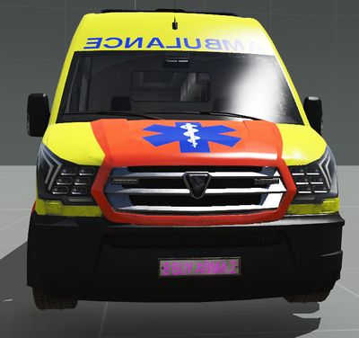
- End result


Scripting commands for plate numbers:
- sets given string to selected vehicle
- returns string with plate number
- Bear in mind that max length of string is limited to 15 characters
Basic Config Hints
Diagnostics
- Drive around as much as possible, preferably using real islands.
- Use Stratis airstrip for acceleration, gear change and sinking of vehicle purposes
- Path from Jay Cove to Airstation Mike-26 on Stratis is great to test uphill performance of the car and AI driving skills
- Whole Chernarus is excellent playground to test vehicles
Suspension
- Easier way to set up suspension is to have center of mass centered according to wheels. Non-centered center of mass is more interesting for driving performance, just be sure to make center of mass centered at least in left-to-right axis.
- Each wheel could have different suspension parameters but try to keep them the same for wheel pairs.
- You may try to use ARB if the car sways a lot sideways during turns. This causes lesser side sway but doesn't reduce bumping of suspension when accelerating and breaking.
Gearbox
- Real gearbox ratios have extremely good results for higher speeds and are realistic for lower speeds. But it is better to use some lower values for lower gears to improve acceleration
- Look out for too big steps between gear ratios, this may prove to be problematic with steep torqueCurve - engine would change gear later than expected and sound would go fubar
- dampingRateZeroThrottleClutchEngaged and dampingRateZeroThrottleClutchDisengaged could be the same, this works really well for FWD cars - engine would slow them down way too much and lock the wheels when only directional arrow is pressed
Reference
This page is discussed on the BI forums.