Dynamic Airport Configuration – Arma 3
Together with Jets DLC, there have been introduced a new feature - which is creating landing strips dynamically, instead of them being hardcoded in the terrain config. This feature was necessary to create and configure for the USS Freedom aircraft carrier, to allow AI and autopilot land there.
For this purpose, a new base class in the core config has been introduced, and by inheriting from this class, there can be created and object placeable even in 3Den editor.
class AirportBase : NonStrategic
{
    simulation = "airport";

    ilsPosition[] = { -270, 0 };
    ilsDirection[] = { -1, 0.08, 0 };
    ilsTaxiIn[] = { 40, -38, -212, -38, -218, -32, -218, -10, -200, 0 };
    ilsTaxiOff[] = { 20, 0, 240, 0, 250, -10, 250, -30, 245, -35, 240, -38, 40, -38 };
};
The parameters above are a series of plotted coordinates, which define the layout and the direction of the airfield. The coordinates used to plot these points are from X,Y,Z positioning system. Unlike with airports in terrain config, where the points are set of an absolute coordinates when it comes to the terrain, dynamic airport's points are relative to the "model centre" - in other words, [0,0] coordinates. Seeing that dynamic airport is a set of nodes, it is often difficult to determine visually, and for creating it's configuration. Personally, I recommend usage of squared paper :)
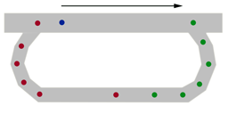
Placing the airport in 3DEN allows to see its shape in the map view (2D map), as well it's rotation. However, in 3D it's basically invisible. This is an example of the airport shape with the configuration above (not rotated in 3DEN):
Airfield parameters
ilsPosition - touchdown / takeoff position. This position has three purposes:
- Position, which the aircraft will aim for the touchdown - quite often the aircraft misses this point and touches down after it, so please keep it in mind when plotting this position
- Start position for the takeoff
- First set of coordinates for ilsTaxiOff position
- Format is [x,y]
- Represented by blue dot on the picture below
ilsDirection - defines the land / takeoff direction as well as the landing glide slope
- There can be only one direction for both landing and takeoff per runway
- Three values need to be input - defining a point in 3D relative to the ilsPosition
- Format is [x,z,y]
- Represented by black arrow on the picture below
- Formula for working out the values (opposite of landing direction - add/subtract 180 from the angle of the direction):
ilsDirection [] = {sin(opposite of desired landing direction in degrees), sin(desired glideslope in degrees), cos(opposite of desired landing direction in degrees)};
ilsTaxiOff - path to taxi off the runway
- A series of X, Y coordinates(waypoints) used by AI to taxi off the end of the runway.
- Represented by green set of dots on the picture below
ilsTaxiIn - path to taxi onto the runway
- A series of X, Y co-ordinates (waypoints) used by AI to taxi on to the start of the runway.
- Represented by red set of dots on the picture below
Aircraft carrier landing strip
note: tailhook = true;

