Vehicle Hitpoint Creation – Arma 3
Jump to navigation
Jump to search
| Line 38: | Line 38: | ||
###...that the sphere matrix should be a completely regular 3D grid--the distance between each sphere should be identical | ###...that the sphere matrix should be a completely regular 3D grid--the distance between each sphere should be identical | ||
###...that the FG should be evenly encased by your HP sphere matrix. It's as if you converted the FG into a voxel network of spherical cells--part of the FG should not be sticking out of the sphere matrix. | ###...that the FG should be evenly encased by your HP sphere matrix. It's as if you converted the FG into a voxel network of spherical cells--part of the FG should not be sticking out of the sphere matrix. | ||
##[[File:hitpoint guide.JPG]] | ##[[File:hitpoint guide.JPG|300px]] | ||
##You want "A" above (where blue FG is armor and orange FG is an HP component that receives damage). You should avoid "B" (unless you really know what you are doing). Under no circumstances should you have a situation like "C". | ##You want "A" above (where blue FG is armor and orange FG is an HP component that receives damage). You should avoid "B" (unless you really know what you are doing). Under no circumstances should you have a situation like "C". | ||
##It will probably make your life MUCH EASIER if you simply standardize on a HP sphere matrix of a given radius rather than using slightly different radii for different HP. | ##It will probably make your life MUCH EASIER if you simply standardize on a HP sphere matrix of a given radius rather than using slightly different radii for different HP. | ||
Revision as of 21:09, 28 October 2015
Intro
Basic tips about building vehicle fire geometry and hit points. This article assumes you are already pretty familiar with making vehicle addons for Arma 3.
Take a look at these two images. Using the fire geometry LOD of a generic "tank", they tell you a lot about how fire geometry ("FG") and hitpoints ("HP") should be set up:


- Transparent blue: armor FG
- Solid-colored boxes: HP FG
- Transparent spheres: HP spheres (i.e. based on your vehicle config radius values)
The Four Commandments
- Pieces of FG should not overlap (as little as possible anyway).
- Leave some space between different types of FG--between armor and HP, or between one HP component and another. These should DEFINITELY NOT overlap.
- HP FG should be encased within an EVENLY SPACED matrix of HP spheres.
- HP spheres CAN overlap BUT they should only be in contact with ONE type of HP FG.
Refer to the two images in the Intro for visual reference.
More Detail If You Need It
This section is optional, in case you're looking for a more detailed discussion beyond the Commandments section above.
- No overlap
- The less the better, with none being the ideal. A little overlap is most tolerable in pieces of armor, or within a single type of HP FG (e.g. several convex pieces of FG that make up your vehicle's engine compartment).
- No overlap between different FG types
- There should be an airspace buffer between HP FG--which will be taking damage--and armor FG--which should cause marginal to no damage.
- You also need airspace buffer between different HP components (engine, turret, gun, etc.). It's not the exact airspace distance that matters per se, it's that you have to prevent an HP sphere encasing one component from touching a second component. When a sphere touches 2 different types of FG, damage on one component will "leak" to the other.
- Meeting these requirements, you will often find yourself needing something roughly on the order of 12" (25cm) between different FG components.
- Encase FG evenly in HP spheres
- Each HP component should be as evenly encased as possible within a "bubbly" matrix of overlapping HP spheres.
- "Evenly encased" means
- ...that the spheres should overlap with each other to fully encase the FG without leaving gaps
- ...that the sphere matrix should be a completely regular 3D grid--the distance between each sphere should be identical
- ...that the FG should be evenly encased by your HP sphere matrix. It's as if you converted the FG into a voxel network of spherical cells--part of the FG should not be sticking out of the sphere matrix.
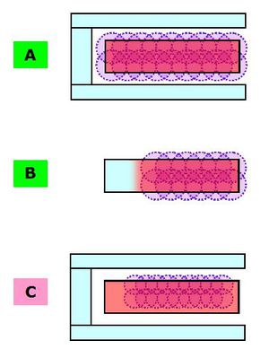
- You want "A" above (where blue FG is armor and orange FG is an HP component that receives damage). You should avoid "B" (unless you really know what you are doing). Under no circumstances should you have a situation like "C".
- It will probably make your life MUCH EASIER if you simply standardize on a HP sphere matrix of a given radius rather than using slightly different radii for different HP.
- This way you can space the "grid" or "matrix" of HP sphere vertices and simply copy and paste the vertices around your HitPoints LOD to appropriately overlap with each Fire Geometry LOD component.
- HP spheres should only touch one type of HP
- This is already explained pretty clearly in 2.2 above.

What Happens If You Don't Follow These Rules
- Weapons which don't penetrate your vehicle's armor will cause damage (even though they shouldn't).
- HP will take totally erratic damage depending on the angle of the weapon impact.
- HP which are not in the path of a penetrating weapon will take damage anyway.
For a much more detailed discussion of vehicular damage, go here. It explains the research behind this article.
Related Links
(The VBS links are very useful, but do contain some obsolete/irrelevant information)
More Detailed Damage Description