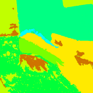
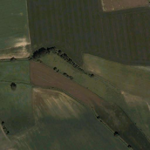
Layered Terrain Surface Representation
Terrain surfaces for the whole world are represented by a pair of textures covering the whole world: Satellite Map and Layer Map. PNG format is used for both textures, both textures are split into segments when imported to Visitor and Layer Map is converted to Layer Mask during the process. Each segment overlaps it is neighbours to allow terrain streaming. The Satellite Map provides basic colour information for displaying distant terrain. As terrain can be visible beyond the range that objects are, representations of objects such as trees, roads, ocean and buildings are all included on the satellite map. The Layer Map and surface types defined in the config determine which terrain textures to display at close distances and other properties.
Note: The import process can be very time consuming because of the huge amount of data being processed. The full import of data for 20x20 km world with resolution 1 takes about 10 hours on a 2 GHz computer. The conversion is incremental, therefore if you edit only a small part of the maps, the next iteration is a lot faster, but it still can take about 1 hour (only launching Buldozer to check the results takes around 15 minutes). Be sure to tune your surfaces with small world first and once you are happy with the results, proceed with the large one.
Layer Legend
Legend is an image accompanied with a config, defining conversion from RGB to layers. Config defines which color represents what surface type. One surface type can be represented by multiple colors, which makes creating smooth blends between multiple surface type pairs possible. Only first line of the image is read, the rest is ignored and can be used for annotations.
There are few limitations imposed on the legend file - main being no color can exist twice in the image. The sample legend was created using gradient Rainbow in Photoshop, with added gradients to black and white on the ends using gradient between two colors.
Config describing basic surfaces for this legend might look like this (the config is part of the layer config described below):
class Legend
{
  picture="layertest\src\mapLegend.png";
  class Colors
  {
    /// color names should correspond to surface layer names
    snow[]={{255,255,255}};
    wetSand[]={{0,0,0}};
    grass[]={{0,255,131},{255,255,0}};
    sand[]={{207,115,0}};
    rock[]={{0,255,255},{121,255,0}};
    mud[]={{0,255,0}};
  }
};
Layer Map
Layer map is edited as an RGB image. Each pixel of the map image is interpreted as follows:
- best matching color in the Legend is found
- based on nearest left and right basic surface corresponding surface blend is used
There is another config file describing the layer map. It defines what legend is used, and it also defines surface materials for basic surfaces. Surface materials used in one layer map need to have all parameters except the textures referenced identical. Textures used should not use SRGB color conversions, which implies _lco texture type should be used.
class Layers
{
  class Grass
  {
    texture="layertest\data\grass_lco.paa";
    material="layertest\data\grass.rvmat";
  };

  class Sand
  {
    texture = "#(argb,8,8,3)color(0.5,0.5,0.5,1)";
    material="layertest\data\sand.rvmat";
  };

  class Rock
  {
    texture = "#(argb,8,8,3)color(0.5,0.5,0.5,1)";
    material="layertest\data\rock.rvmat";
  };

  class Mud
  {
    texture = "#(argb,8,8,3)color(0.5,0.5,0.5,1)";
    material="layertest\data\mud.rvmat";
  };
};

class Legend
{
  // see above
};
Editing Layer Map and Satellite Map
Assume texture folder is defined as LayerTest\Data in the Visitor for given world. All source files are assume to be located in LayerTest\Source unless specified otherwise.
Preparations:
- create a legend image
- create a config layers.cfg defining surfaces and legend used
- in Tools/Project Preferences decide on the satellite map segment size. The segments need to overlap slightly because of texture connecting - good overlap size is around 16 texels. Satellite map segment size is given as a multiple of basic landscape grid.
- Example: Assume world size 10240 x 10240 m with 40 m grid (i.e. 256 x 256 grids) , satellite texture with resolution 7680 x 7680 (one landscape grid needs to be covered by a whole number of texels, therefore satellite texture size needs to be a multiple of world size in grids). We want to achieve segment size 512 x 512 texels, and given the 16 texel overlap wanted, one segment will cover 496 x 496 texels. Size of one texel is 10240 m /7680 (1.3333 m) in this case, 496 texels give around 661.33 m. With 40 m grid we get 661.33/40 = 16.5, which rounded down gives 16. (If the texture grid is different from the terrain grid, rounding down is not enough - we need to round down to the nearest multiple of the number of terrain grids in the texture grid. With terrain grid 10 and texture grid 40 the satellite segment size needs to be a multiple of 4.
Editing cycle: (editing is usually done in Photoshop with Buldozer not running)
- edit satellite map in Photoshop (file Satellite-map_lco.png). Note: you need to use _lco or _draftlco as a texture type.
- edit layer map mask in Photoshop (file Layer-map_lco.png). Note: you need to use _lco or _draftlco as a texture type.
- run Tools / Import Satellite + Mask, select Satellite-map_lco.png, Layers.cfg, Layer-map_lco.png files in the file browser
- run Buldozer to check the result
Textures
Each terrain type is represented at close distance by a colour only (CO) texture and a normal map (NO*). On SaraLite, each 1024x1024 pixel detail covers about 4m. Each pixel of the layer mask covers about 2m.
Terrain types also have an associated MCO texture. This is a greyscale texture that is multiplied with the satellite map to provide middle distance details. On SaraLite, each 1024x1024 MCO texture covers about 40m (one terrain texture grid cell). The engine loads terrain textures one texture grid at a time, each segment being made up into 12x12 texture grids, plus the overlapping 32 pixels.
Game Engine Notes
The information about the layer map above relates to tool use rather than the ArmA game engine. For game engine use each segment of the Layer map uses its own pallete that is unrelated to the Layer Legend mentioned above. Each terrain type within a segment uses a colour based upon the order in which the terrain types are defined in the config. Colours are used in the following order : Black (000000), Red (FF0000), Green (00FF00), Blue (0000FF). This method of defining terrain types restricts each segment to a maximum of four different terrain types. All 4 terrain types can be blended together within one pixel of the layer map (2m x 2m on Sahrani), although blending is rarely used. Ground clutter appears to be placed based upon the dominant terrain type.
There are several RVMAT configs for each segment, each defining a PixelShaderID. Each combination of terrain types within each of the texture grids within one segment requires it is own RVMAT.


