Visitor 3 Manual: Difference between revisions
Lou Montana (talk | contribs) m (Text replacement - "lenght" to "length") |
|||
| (118 intermediate revisions by 12 users not shown) | |||
| Line 1: | Line 1: | ||
{{TOC|side}} | |||
=== Updated Information === | |||
::from [[User:Mikero|Mikero (nee Ook?)]] 03:52, 29 November 2010 (CET) | |||
Apart from any other oddness, this manual appears to conflict with the 'real world' use of buldozer.exe as supplied in [[BI_Tools_2|BI Editing Tools 2]]. Buldozer.exe is incompatible with the general needs of the developer community in producing their own '''P:\''' drive. Specifically, '''\bin''' and '''\core''' *must* reflect the engine's '''bin''' and '''core.pbo'''. Buldozer (of course) uses it is own. | |||
If you have produced your own '''P:\''' drive which properly reflects all the extracted PBOs of your engine you need to replace '''buldozer.exe''' with your engine's EXE. E.g. Arma2OA.exe, arma2.exe or whatever. Move the original '''buldozer.exe''' from '''P:\''' to any folder and copy your engine's EXE to '''P:\''' and rename it '''buldozer.exe'''. | |||
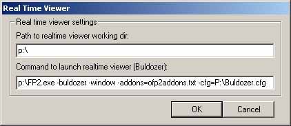
Real Time Viewer settings: '''Tools''' menu > '''System Preferences''' command. Real Time Viewer window appear. In '''Real time viewer settings''' field you can change path to real time viewer working directory (default "P:\") and command to launch real time viewer (Buldozer) in appropriate lines (default "P:\buldozer.exe" -window -buldozer -addons=p:\V3addons.txt). | |||
NOTE: | |||
* pointing '''System Preferences''' to anything other than the root of '''P:\''' is not garanteed to work. Ditto for Oxygen | |||
* steam EXEs are not usable. (betas are) | |||
* P:\dta\product.cpp '''must''' be original buldozer's product.bin. This because it is looking at registry settings for font sizes. | |||
* only the highest order EXE works. If you have arma2.exe and Arma2OA.exe, you need Arma2OA.exe. | |||
Any of the other '''-options''' mentioned in this document may or may not work but appear to be irrelevant / erroneous. The bottom line criteria is | |||
* Visitor p:\buldozer.exe -buldozer -window | |||
* Oxygen p:\buldozer.exe -buldozer -window -noland | |||
To close the buldozer window press {{Controls|Alt|F4}}. | |||
=== Introduction === | |||
This manual will explain the basic functions of Visitor3, the landscape editing tool for Arma. | |||
Version 3 of the Visitor tool has some improved features over its precedessors: | |||
* Easier object handling | * Easier object handling | ||
* All operations are much faster (especially with large number of objects | * All operations are much faster (especially with large number of objects | ||
* Support for surface materials rvmat and new transition materials bimpas | * Support for surface materials rvmat and new transition materials bimpas | ||
* Import/Save landscape profiles from/to images (.png format) | * Import/Save landscape profiles from/to images (.png format) | ||
* | * Complete in English | ||
* Improved | * Improved networks creation | ||
* Script support | * Script support | ||
* Background overlay images | * Background overlay images | ||
* Source control integration | * Source control integration | ||
* Reworked and polished UI allowing docking of toolbars etc. | * Reworked and polished UI allowing docking of toolbars etc. | ||
There are some recently added or developed features, which are not present in Personal Edition of V3 and are described elsewhere. | |||
=== | === Installation & Setup === | ||
To be able to export WRP file of your map, you need to have Arma installed on your system. Arma running in Buldozer mode acts as 3D viewer and exporting tool for WRP file. | |||
First you should do is to click ''Tools\System Preferences'' to set the path to realtime viewer working directory (''P:\'' is standard ). All path indications will be relative to this path, so if something does not work as expected you should check there first. | |||
Also define the call parameters for the viewer: | |||
Syntax: | |||
''PathToArma\Arma.exe [-window] [-cfg=PathToConfig]'' | |||
[[ | Commands in [] are optional (leave [] away when using that command): | ||
''PathToArma'' : Path to the folder where Arma.exe is located, this is the path to game installation. | |||
''-window'' : Buldozer starts in window mode instead of fullscreen. | |||
''-cfg=PathToConfig'' : Forces Buldozer to use a certain config. By default Buldozer uses same settings as the game, located in ''c:\Documents and Settings\USERNAME\My Documents\ArmA\ArmA.cfg'', but you may as well use your own config located wherever you fancy, provided you state the path correctly. | |||
''-addons=ArmaAddons.txt'' : File containing list of addons which are used when Arma runs in Buldozer mode. Particularly useful for UI elements required for your work in Buldozer (arrow, box cursor), as well as for other unnecessary things like skies or clutter. Content of TXT file is refering to unpacked data on your working disc (P:\), not to PBOs in game installation. ArmaAddons.txt must be located on the root of disk P, it is a list of addons, configs of the listed addons will be used. E.g. if you want to see correct clutter settings for edited world, its folder must be mentioned in p:\ArmaAddons.txt. | |||
''-connect=pipe\anyNameYouLike'' : Use named pipe and specify its name, usefull especially when debugging, not required for end-users. | |||
Example of file ArmaAddons.txt with paths to addons: | |||
<syntaxhighlight lang="cpp"> | |||
addons[] = | |||
{ | |||
"ca\", "ca\data\", "ca\UI\", "ca\UIFonts\" | |||
}; | |||
</syntaxhighlight> | |||
Mind that described path must end with backslash - \, otherwise it will be considered as file, not path. | |||
Typical setup of realtime viewer parameters: | |||
[[File:vis_w_SystemPref.JPG]] | |||
o:\arma\Arma2Int.exe -buldozer -window -addons=ofp2addons.txt -maxmem=1024 | |||
It is also possible not to specify the viewer exe. This tells Visitor it should only create the pipe and listen to any incoming connections on it. This is handy when launching the viewer externally. Options other than ''-connect'' are ignored when used this way. | |||
-connect=pipe\Visitor | |||
=== Interface === | |||
Most of the buttons are self-explanatory, so only the important ones should be explained. | |||
If you used old Visitor, you will notice that the buttons for selections and object handling disappeared. This is now handled over a combination of Shift\Ctrl and mouse buttons. | |||
Most important in first line of tool buttons are [[File:vis_b_buldozer.JPG]] (Connect\disconnect to Buldozer) and [[File:vis_b_alignToWindow.JPG]] (Fit to window). | |||
[[File:vis_b_Filter.JPG]] | |||
contains additional filters and view options. | |||
The actual view is shown in the map window: | |||
[[File:vis_w_currentmap.JPG]] | |||
The current editor mode is shown in this window: | |||
[[File:vis_w_currentediting.JPG]] | |||
* | ==== Navigation in Map View ==== | ||
* {{Controls|MMB}} - pointing location. | |||
* {{Controls|RMB}} - panning the map. | |||
* {{Controls|Ctrl|J}} - to get to cursor location. | |||
* | ==== Objects and areas selection ==== | ||
* {{Controls|LMB}} - place or select/deselect objects and surfaces. | |||
* Press-hold {{Controls|LMB}} and move the mouse over the area - select it. | |||
* {{Controls|Ctrl|LMB}} - including areas to the selected one. | |||
* {{Controls|Shift|LMB}} - excluding areas. | |||
* {{Controls|LMB}} on an object - select it. | |||
* {{Controls|Ctrl|LMB}} or press-hold the {{Controls|LMB}} and drag a selection box around several objects - select them. | |||
* Press-hold {{Controls|Ctrl}} or {{Controls|Shift}}, click {{Controls|LMB}} on them and move the mouse up or down -rotate one or several selected object(s), . | |||
=== Basic Map Processing === | |||
Detailed tutorial describing basic map making process can be found in [[Visitor 3: Making of simple landscape]]. | |||
'''Getting started:''' | |||
* Create new project: Project > New ({{Controls|Ctrl|N}}) | |||
* In ''Project parameters'' box > Terrain size field: set Terrain grid size and Terrain cell size. | |||
* Set project preferences ( Tools > Project preferences... ), fill in ''PathToMap\data'' to Folder - Textures field. | |||
* To insert objects or roads, you will first need to define them in their respective lists accessible in Tool menu: Natural Objects, Artificial objects, Roads etc. | |||
* To import surface textures, use Tools > Import Satellite&Mask (for detailed info on the subject see [[Making Satellite Texture and Mask]] and [[Layered Terrain Surface Representation]]). | |||
'''To export your map:''' | |||
* Open realtime viewer (Project > Connect to Buldozer, {{Controls|Ctrl|F7}}). Realtime viewer has to be running when exporting .WRP file. | |||
* To export your map for the engine, select Project > Export world..., and store it to YourMap\YourMap.wrp. YourMap.hpp is stored in the same location, containing reference of keypoints (elements of 2D map). | |||
=== Tools === | |||
==== | ==== Textures ==== | ||
===== {{Name|arma1|short}} ===== | |||
In new engine, surface textures are not controlled from the toolbox. Instead of groups of texture squares, surfaces are composed from several layers, as described in [[Layered Terrain Surface Representation]], main input are: | |||
* satellite texture (PNG) - equivalent of aerial photo | |||
* surface mask (PNG, discrete colours) | |||
* layers.cfg - definition of surfaces contained in the surface mask, based on their RGB values | |||
These data are imported using '''Import satellite & mask''' option in Tools menu. This causes deleting of all previous surface definitions, segments of satellite texture and mask are generated to folder specified in '''Project Preferences''' as Textures folder. | |||
In toolbox, there is only definition of texture layer size, which can be edited by {{Controls|RMB}} on its name in the list. | |||
===== {{Name|ofp|short}} ===== | |||
This describes how surfaces were edited in older version of engine ({{ofp}}). Terraintextures and surfaces definitions (the final terrain properties are made in the config). | |||
All surfaces/terrain surface definitions are made here. Visitor works with 2 types of textures: main textures (Primary and variants textures) and transisition textures. While you have to provide the first type, transition textures are created by Visitor to blend the transitions from one texture to another. | |||
[[File:vis_t_terrDef.JPG]] | |||
* "New...": Define a new terrain type. | |||
* "Add": Add a surface type to a terrain type. | |||
[[File:vis_t_terrTextures.JPG]] | |||
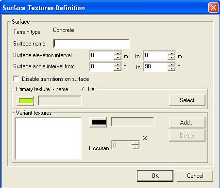
* Disable transitions on surface: Forces Visitor to create no transition textures between different terraintextures. | |||
* "Select": Select primary texture. Note that you have to keep the name under 20 characters, so delete long paths from the name. Also keep in mind that the path is a relative path, so you have to force a folder stucture similar to the OFP2 structure. | |||
* "Add": Adds variant textures. Here aswell a maximum of 20 characters in named are allowed. | |||
* Occuran: Chance in percent that this variant of a texture is selected. | |||
==== Natural Objects ==== | |||
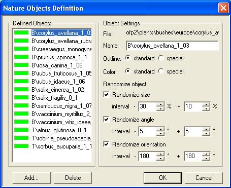
All vegetation is defined in the Nature Objects Definition box. You can use Natural objects filter button in main toolbar to hide or unhide them. | |||
[[File:vis_t_natobj.jpg]] | |||
==== Artificial Objects ==== | |||
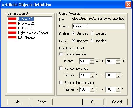
All artificial objects are defined in the Artificial Objects Definition box. Artificial objects filter button can be used to hide or unhide them. | |||
[[ | [[File:vis_t_artobj.jpg]] | ||
'''Values of adjustments''' | |||
* | * "Add": Add an object, browse the opening list to select the model you want to use. | ||
NOTE: the maximum length of the name - 50 characters. | |||
* Randomize size intervall: Model size will be randomly set in the given interval. | |||
* Randomize angle interval: Model angle will be randomly set in the given interval. | |||
* Randomize orientation interval: Model facing direction will be randomly set in the given interval. | |||
Randomness happens as well during insertion objects placed by a script. | |||
==== Roads ==== | |||
Road types and road sections are defined here. Each road consists of curved parts and straight parts with standard dimensions. For each road, curved and straight parts should be defined, as well as terminator segments (6.25 m segment with fading texture). Crossroads are special cases which need to have suitable road types defined for each of their ending direction. | |||
* To start new road, {{Controls|LMB2}} on the map when '''Road network''' is selected in the toolbox. New key segment is created (any segment may become key segment) and road can be edited for every available direction (ending - one direction, curves and straight parts - two directions, crossroads - 3-4 directions). | |||
* To edit existing road, {{Controls|LMB2}} on it to access main editing dialogue. | |||
[[File:vis_t_roadsMain.JPG]] | |||
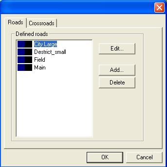
After hitting "Add" or "Edit" the Main setting window for the road shows up. | |||
* | * Road: Main settings for given road type. | ||
[[File:vis_t_roadsDef.JPG]] | |||
* Straight Parts: all straight sections of this road type. | |||
NOTE: those parts need a certain length: 6.25, 12.5 or 25 meters. | |||
[[File:vis_t_roadsAddType.JPG]] | |||
[[File:vis_t_roadsAddTypeDef.JPG]] | |||
* Curves: all curved section of this road type. | |||
NOTE: those parts need a certain radius: 25, 50, 75 or 100 meters. | |||
[[File:vis_t_roadsCurveDef.JPG]] | |||
* Special Parts: sections with a T-shape. | |||
* Terminators: Sections that ends a road. | |||
[[File:vis_t_roadsTermDef.JPG]] | |||
==== | ==== Project Preferences ==== | ||
Paths to textures and objects (if stored in a specific place) and other project specific settings. | |||
[[File:vis_t_ProPref.JPG]] | |||
* Folder - Textures: Path to the folder where all lanscape textures are stored. | |||
NOTE: the path is relative in the map, so you have to maintain the folder structure. | |||
* Folder - Objects: Path to the folder where all objects are stored. This path is relative. | |||
* Square Size: the side length of the square in game. | |||
==== | ==== Project Parameters ==== | ||
Project parameters contain basic information about the project size. Most information is edited when project is started, later only Satellite grid and Texture layers dialogues are accessible. | |||
==== Object Manager ==== | |||
There are only two functions. | |||
NOTE: Visitor MUST NOT be connected to realtime viewer when using these functions. | |||
If size of resolution LOD or Geometry LOD of a custom model changed, these functions are useful to give Visitor updated object description or to fix object shifts in vertical axis, including recalculation of all objects to relative elevation to surface =0. | |||
==== Exchange Objects ==== | |||
Deletes or replaces all instances of an object (models) from the map. | |||
[[File:vis_t_ReplObj.JPG]] | |||
==== Snap Objects ==== | |||
Closes small gaps that can occur when placing objects like fences, walls. | |||
NOTE: objects need to be prepared for snapping. | |||
===Editing Modes [F1-F10]=== | === Editing Modes [F1-F10] === | ||
==== | ==== Artificial Objects [F1] ==== | ||
Placing | Placing artificial objects, except roads. | ||
[[ | [[File:vis_em_artobj.jpg]] | ||
Select an object and click LMB on the map where you want to place it. | |||
==== Natural Objects [F2] ==== | |||
Placing natural objects, except forest. | |||
[[File:vis_em_natobj.jpg]] | |||
Select an object and click LMB on the map where you want to place it. | |||
==== New road objects [F3] ==== | |||
list of new roads. | |||
==== | ==== Road networks [F4] ==== | ||
Placing roads. | Placing roads. | ||
[[ | [[File:vis_em_nets.JPG]] | ||
Select a road type and click LMB on the map where you want to place it. A dialog will appear leading you through the placement process. | |||
NOTE: You only have to place the first key part of a road section. Then you can simply click LMB on the map and Visitor will try to reach the point automatically. You can do it manually. If you click LMB on a placed road, the road property window will appear. | |||
[[ | [[File:vis_em_RoadsProperties.JPG]] | ||
Every road part | Every road part, except terminators, have two main directions: A and B, reflecting both ends of key section. Visitor uses the closest end of a road to reach a point on the map. | ||
* Orientation Of Key Part (Direction A): Direction the A end is facing, angles are only possible in 10° | * Orientation Of Key Part (Direction A): Direction the A end is facing, angles are only possible in 10°/step. | ||
* Position X and Position Z: | * Position X and Position Z: position of the key part on the map. | ||
* Gen.Terminator: | * Gen.Terminator: Create Terminator or new Key section at the end of direction | ||
* Modify Dir. A: | * Modify Dir. A: | ||
[[ | [[File:vis_em_RoadsDirect.JPG]] | ||
Note: | Note: Deleting or Adding a part in the middle of the road changes the rest of the road. Added sections will be inserted before the section marked in "All Parts Of This Direction". | ||
* All Parts Of This Direction: All sections from the key section to the end of the road | * All Parts Of This Direction: All sections from the key section to the end of the road | ||
| Line 248: | Line 308: | ||
* Special: Adds the selected special section to the road. | * Special: Adds the selected special section to the road. | ||
==== Key points [F5] ==== | |||
====Key | |||
Display/Create key points. | Display/Create key points. | ||
List of all key points on the map. To add key points, click LMB on the map in this editing mode. | List of all key points on the map. To add key points, click LMB on the map in this editing mode. | ||
[[ | [[File:vis_em_keypoints.JPG]] | ||
Same options as in [[#Named Zones [F6]]] editing mode. | Same options as in [[#Named Zones [F6]]] editing mode. | ||
==== | ==== Terrain vertices [F6] ==== | ||
Landscape height changing. Landscape forming tool. | Landscape height changing. Landscape forming tool. | ||
| Line 290: | Line 324: | ||
[[ | [[File:vis_em_LandVertexes.JPG]] | ||
Change Height: Changes the height of points/area on the map. | Change Height: Changes the height of points/area on the map. | ||
[[ | [[File:vis_em_LandVertexesHeight.JPG]] | ||
* Change only: Shows only up when the selection has sea and land points. | * Change only: Shows only up when the selection has sea and land points. | ||
Ground (Positive Height): Only points over | Ground (Positive Height): Only points over sealevel will be changed. | ||
Sea (Negative Height): Only points below | Sea (Negative Height): Only points below sealevel will be changed. | ||
* Minimal Height: All points will set to the height of the lowest point of selection. | * Minimal Height: All points will set to the height of the lowest point of selection. | ||
* Median Height: All points will set to the median height of selection. | * Median Height: All points will set to the median height of selection. | ||
* Maximal Height: All points will set to the height of the highest point of selection. | * Maximal Height: All points will set to the height of the highest point of selection. | ||
* | * Averange Height: All points will set to the averange height of selection. | ||
* Height: All points will set to this height. | * Height: All points will set to this height. | ||
* Transform Into | * Transform Into Intervall: Takes the current height profile of selection and stretches it into the given intervall. | ||
Erosion: Erodes Landscape. | Erosion: Erodes Landscape. | ||
[[ | [[File:vis_em_LandVertexesErosion.JPG]] | ||
* nGens: Number of generations of erosion (max. 128 generations). | * nGens: Number of generations of erosion (max. 128 generations). | ||
* WashCoef: Wash | * WashCoef: Wash Coeficiant, how strong does water flow affect terrain. | ||
* SedimCoef: Sediment | * SedimCoef: Sediment Coeficiant, how fast sediments sink down and stay where they are. | ||
* SedimBase: Sediment Base, how much sediment is there from the beginning. | * SedimBase: Sediment Base, how much sediment is there from the beginning. | ||
* SedimEff: Sediment Effect, "wash out" resistance of terrain. | * SedimEff: Sediment Effect, "wash out" resistance of terrain. | ||
* Initrain: | * Initrain: Strenght of rain. | ||
* SteadyRain: How long does the rain last. | * SteadyRain: How long does the rain last. | ||
* FinalBlur: Creates a smoother surface. | * FinalBlur: Creates a smoother surface. | ||
====Background | ==== Background images [F7] ==== | ||
Sets a | Sets a background picture as reference. | ||
[[ | NOTE: only .bmp format are supported. | ||
[[File:vis_em_backPic.JPG]] | |||
To see the background image, in the "Create background image" dialogue (below), first choose some BMP file. Placement values are coordinates for top left corner (for the image covering whole map, set both to 0). Width and Height are true sizes of imported image. ''Example: If the map is e.g. 10240x10240 meters and the background image covers whole area, set Width and Height values to 10240.'' | To see the background image, in the "Create background image" dialogue (below), first choose some BMP file. Placement values are coordinates for top left corner (for the image covering whole map, set both to 0). Width and Height are true sizes of imported image. ''Example: If the map is e.g. 10240x10240 meters and the background image covers whole area, set Width and Height values to 10240.'' | ||
Smaller hi-res images can be used as well, if the coordinates and size are set correctly. | Smaller hi-res images can be used as well, if the coordinates and size are set correctly. | ||
[[ | [[File:vis_em_backPicCreate.JPG]] | ||
==== Named zones [F8] ==== | |||
Display/Create named zones. | |||
List of all named zones on the map. To name a zone click LMB on map screen the selection box. | |||
[[File: vis_em_namedzones.JPG]] | |||
* Go To...: Centers view on selected zone. | |||
* Properties: Opens properties window (same as doubleclicking the selection). | |||
* Select area under zone: | |||
* Select Objects In Zone: Selects all objects that are in this zone. | |||
... | |||
===Terrain=== | ==== Named objects [F9] ==== | ||
Browser for all named objects on the map. | |||
[[File:vis_em_namedobj.JPG]] | |||
==== Surfaces (OFP) [F10] ==== | |||
Sets textures/properties to surfaces. | |||
[[File:vis_em_LandTex.jpg]] | |||
* Terrain type: Current selected terrain type. | |||
* Surfaces: Current selected surface. | |||
* Textures: Current selected texture, if set to "random selection" it will randomly choose on of the available textures. | |||
* Set Texture Onto Area: Set current texture on selected area. | |||
* Set Surface Onto Area: Set current surface on selected area. The textures are set according to their probabilities. | |||
* Set Terrain Onto Area: Set current terrain on selected area. The surfaces are set according to their definition. Same for the textures. | |||
* Change Texture Onto Area: Changes texture in area to current selected texture. | |||
* Texture Analysis..: | |||
==== Woods [F11] ==== | |||
Creating forests as they were in Operation Flashpoint maps. Obsolete and kept only for backwards compatibility. | |||
=== Terrain === | |||
You have several options to edit the height profile of your map: | You have several options to edit the height profile of your map: | ||
* Manually ("Landscape - Vertexes" as editor mode/F9): This is the most work intensive version, you change all landscape point individually. We recommend to use this method only for | * Manually ("Landscape - Vertexes" as editor mode/F9): This is the most work intensive version, you change all landscape point individually. We recommend to use this method only for finetune a map. | ||
* Import ASE Height Map (Projects/Import Terrain): Read in an 3D Studio Max .ase height map. This will be more likely removed in future. | * Import ASE Height Map (Projects/Import Terrain): Read in an 3D Studio Max .ase height map. This will be more likely removed in future. | ||
| Line 352: | Line 433: | ||
* Import from XYZ map (Projects/Open "Files of type: *.xyz"): XYZ is ASCI file format | * Import from XYZ map (Projects/Open "Files of type: *.xyz"): XYZ is ASCI file format contaiting space delimited X Y Z on each line, where XY is UTM and Z is in meters. During import you can align data to top or bottom left and set target data dimension to crop data or extend area. | ||
* Inside Buldozer: You can use U (small step up), I (big step up), J (small step down) and K (big step down). This is also best used for | * Inside Buldozer: You can use U (small step up), I (big step up), J (small step down) and K (big step down). This is also best used for finetune the profile. | ||
NOTE: for import terain operations (and any other large scale operations like this) it is recommended to disonnect Buldozer otherwise it takes really long time to process the map. | |||
===Scripts=== | === Scripts === | ||
Visitor 3 gives you the opportunity to use scripts for certain tasks. | Visitor 3 gives you the opportunity to use scripts for certain tasks. | ||
Scriptfiles have the ending .vis. | |||
We use the OFP own scripting language with some extensions. For all possible command see the Visitor Script Command Reference | |||
For some examples see Script folder in the directory you found this HTML file. | |||
===Your Old Flashpoint Map Project to Arma Map Project By Ivan== | === DEM Files Manipulation and Export === | ||
Visitor 3 can't import of DEM files but you can easily convert DEM files to XYZ files using 3rd party software. | |||
First choice for this task is MicroDEM. How to export DEM to XYZ from Microdem 6.03: | |||
* Start Quickview application from Microdem folder. | |||
* Select File -> Data Manipulation to open Data Manipulation window (or alternatively click at In<->OutIcon in the Microdem's toolbar). Note that you must select this mode before you do any other actions in Microdem, otherwise it is disabled. | |||
* In Data Manipulation window select Export -> ASCII XYZ, full DEM, open DEM file you want to export and select XYZ file. You're promted to ask coordinates units, use UTM for XY and meters for Z. | |||
Tips and tricks: Another good and freely available DEM utility is 3dem. It's more user friendly and faster than MicroDEM in many operations. The fastest and most compatible file format to use to transfer files from 3dem to Microdem is GeoTiff. Here are some of tips and tricks how to process DEM data using 3dem and Microdem to prepare them for Visitor: | |||
* Patch missing DEM data to avoid holes in the map: Operation -> Patch missing data in 3dem; Edit -> Fill DEM holes in Microdem Data Manipulation. | |||
* Resample DEM to desired size and resolution: In Microdem Data Manipulation Resample - DEM, change X, Y spacing from current value to desired value | |||
* Merge DEMs: In 3dem just open multiple DEM files at the same time to merge them; in Microdem Datamanipulation select Merge -> DEMs, consequently open DEM files you want to merge, press cancel in Open merging file selector after last DEM is added and fill the target file name in merged DEM file selector. | |||
* Crop DEM: In 3dem, use Operation -> Select Smaller Area, select the area and press Enter; in Microdem Data Manipulation use Subset -> DEM rectangle and select the method you prefer. | |||
=== Advanced Surface Editing === | |||
[[Layered Terrain Surface Representation]] | |||
== Your Old Flashpoint Map Project to Arma Map Project By Ivan == | |||
To avoid conflicts arising from simultaneous use of old and new projects in V3, the idea is to have a clone of the old project and transferring there old content using scripts. Since Visitor works with '''VISITOR OBJECT NAMES''', not with '''MODEL NAMES''', it makes the task easy. Keep old project untouched as reference and source for exporting content. | To avoid conflicts arising from simultaneous use of old and new projects in V3, the idea is to have a clone of the old project and transferring there old content using scripts. Since Visitor works with '''VISITOR OBJECT NAMES''', not with '''MODEL NAMES''', it makes the task easy. Keep old project untouched as reference and source for exporting content. | ||
Tutorial is based on assumption that you have '''p:\''' as virtual working drive. | Tutorial is based on assumption that you have '''p:\''' as virtual working drive. | ||
==== Make Target Project ==== | |||
You will need to make project with same dimensions as old OFP map. | You will need to make project with same dimensions as old OFP map. | ||
- Make new project in Visitor. | - Make new project in Visitor. | ||
- Specify width/height: ''12800 m''. Square size is ''50 m''. | - Specify width/height: ''12800 m''. Square size is ''50 m''. | ||
====Project Preferences | ==== Project Preferences ==== | ||
Let's set paths to objects and correct satellite grid number. For Arma maps, we use following settings in Project Preferences: | Let's set paths to objects and correct satellite grid number. For Arma maps, we use following settings in Project Preferences: | ||
Textures folder: '''p:\ca\abel\data''' | Textures folder: '''p:\ca\abel\data''' | ||
Objects folder: '''p:\''' (We can use all objects from all available PBOs this way, you will be able to use Arma objects this way). | Objects folder: '''p:\''' (We can use all objects from all available PBOs this way, you will be able to use Arma objects this way). | ||
Square size: should be 50 meters in your case | Square size: should be 50 meters in your case | ||
Satellite grid: Calculate proper number using the tutorial [[Layered Terrain Surface Representation]], OpenOffice table | Satellite grid: Calculate proper number using the tutorial [[Layered Terrain Surface Representation]], OpenOffice table or updated version of V3. The goal is to enter correct number so that Visitor will cut imported HUGE texture into 512x512 bits. 512x512 is important, it is best choice for good performance. | ||
I used value 16 for Abel, "satellite" texture size was 6400x6400 px. | I used value 16 for Abel, "satellite" texture size was 6400x6400 px. | ||
====Detail Texture Resolution Setting==== | ==== Detail Texture Resolution Setting ==== | ||
You need to set proper size of area, on which detail textures will be mapped. On Arma islands, we use 40 meters, all textures are made in order to fit to this size. You will probably need to tweak size of original textures to fit your map's values. Clutter density values can be updated accordingly. | You need to set proper size of area, on which detail textures will be mapped. On Arma islands, we use 40 meters, all textures are made in order to fit to this size. You will probably need to tweak size of original textures to fit your map's values. Clutter density values can be updated accordingly. | ||
- Make sure you have Panel of Objects visible (set in View menu). In Panel of Objects, choose "landscape-textures" from first roll-down menu. | - Make sure you have Panel of Objects visible (set in View menu). In Panel of Objects, choose "landscape-textures" from first roll-down menu. | ||
| Line 392: | Line 493: | ||
- Resolution IS important. Note that available values are ([terrain size]*2expN). For big maps, you may use quite big number (~100-200 meters, ugly look guaranteed). For Abel, I chose 50x50 meters. Using Sahrani surfaces as they are will thus make them look 1.25x bigger, they stretch on surface 25% bigger than on Sahrani. | - Resolution IS important. Note that available values are ([terrain size]*2expN). For big maps, you may use quite big number (~100-200 meters, ugly look guaranteed). For Abel, I chose 50x50 meters. Using Sahrani surfaces as they are will thus make them look 1.25x bigger, they stretch on surface 25% bigger than on Sahrani. | ||
==== Objects ==== | |||
Transferring objects is not a big issue. You just need to name new object in new project EXACTLY SAME as in old one. Then you may use two ways of inserting objects. | Transferring objects is not a big issue. You just need to name new object in new project EXACTLY SAME as in old one. Then you may use two ways of inserting objects. | ||
- E.g. there is object "kostelik" (=little church) in old project. Path to model is ..\Data3d\kostelik.p3d. In new project, make object with same visitor name, updated Arma counterpart is ..\ca\buildings\kostelik.p3d | - E.g. there is object "kostelik" (=little church) in old project. Path to model is ..\Data3d\kostelik.p3d. In new project, make object with same visitor name, updated Arma counterpart is ..\ca\buildings\kostelik.p3d | ||
- Now the first way of copying it, quite suitable for copying vegetation because it saves relative size of object: Select objects of this kind in old project, copy them (Ctrl | - Now the first way of copying it, quite suitable for copying vegetation because it saves relative size of object: Select objects of this kind in old project, copy them ({{Controls|Ctrl|C}}). In new project, go to "Edit"-> "Paste absolute" (or {{Controls|Shift|V}}) and objects should be copied on their exact locations. | ||
- Second way is script way: We made ExportObjects and ImportObjects scripts, which are part of V3 distribution. You may add them to menu by going to "Scripts"->"Manage scripts", then add them from your Visitor3\Scripts. They are ExportObjects_100.vis and ImportObjects_100.vis. Now you can export data from old project (use default settings, specify path to *.txt file) and import them into new one. | - Second way is script way: We made ExportObjects and ImportObjects scripts, which are part of V3 distribution. You may add them to menu by going to "Scripts"->"Manage scripts", then add them from your Visitor3\Scripts. They are ExportObjects_100.vis and ImportObjects_100.vis. Now you can export data from old project (use default settings, specify path to *.txt file) and import them into new one. | ||
==== Forests ==== | |||
You can forget about old forests. My suggestion is to either compose forest square mock-up and copy it or make new ones. | You can forget about old forests. My suggestion is to either compose forest square mock-up and copy it or make new ones. | ||
{{Feature|important| Note: The number of tree types used in forests significantly affects performance (especially the CPU load).}} | |||
==== Roads ==== | |||
Same thing as 4. You will need to define all road parts in the same way as in original project. Then you just copy them and Paste-Absolute them into new one. Correct counterparts should be selected. | Same thing as 4. You will need to define all road parts in the same way as in original project. Then you just copy them and Paste-Absolute them into new one. Correct counterparts should be selected. | ||
{{GameCategory|arma1|Terrain Editing}} | |||
Latest revision as of 21:37, 27 April 2024
Updated Information
- from Mikero (nee Ook?) 03:52, 29 November 2010 (CET)
Apart from any other oddness, this manual appears to conflict with the 'real world' use of buldozer.exe as supplied in BI Editing Tools 2. Buldozer.exe is incompatible with the general needs of the developer community in producing their own P:\ drive. Specifically, \bin and \core *must* reflect the engine's bin and core.pbo. Buldozer (of course) uses it is own.
If you have produced your own P:\ drive which properly reflects all the extracted PBOs of your engine you need to replace buldozer.exe with your engine's EXE. E.g. Arma2OA.exe, arma2.exe or whatever. Move the original buldozer.exe from P:\ to any folder and copy your engine's EXE to P:\ and rename it buldozer.exe.
Real Time Viewer settings: Tools menu > System Preferences command. Real Time Viewer window appear. In Real time viewer settings field you can change path to real time viewer working directory (default "P:\") and command to launch real time viewer (Buldozer) in appropriate lines (default "P:\buldozer.exe" -window -buldozer -addons=p:\V3addons.txt).
NOTE:
- pointing System Preferences to anything other than the root of P:\ is not garanteed to work. Ditto for Oxygen
- steam EXEs are not usable. (betas are)
- P:\dta\product.cpp must be original buldozer's product.bin. This because it is looking at registry settings for font sizes.
- only the highest order EXE works. If you have arma2.exe and Arma2OA.exe, you need Arma2OA.exe.
Any of the other -options mentioned in this document may or may not work but appear to be irrelevant / erroneous. The bottom line criteria is
- Visitor p:\buldozer.exe -buldozer -window
- Oxygen p:\buldozer.exe -buldozer -window -noland
To close the buldozer window press Alt + F4.
Introduction
This manual will explain the basic functions of Visitor3, the landscape editing tool for Arma.
Version 3 of the Visitor tool has some improved features over its precedessors:
- Easier object handling
- All operations are much faster (especially with large number of objects
- Support for surface materials rvmat and new transition materials bimpas
- Import/Save landscape profiles from/to images (.png format)
- Complete in English
- Improved networks creation
- Script support
- Background overlay images
- Source control integration
- Reworked and polished UI allowing docking of toolbars etc.
There are some recently added or developed features, which are not present in Personal Edition of V3 and are described elsewhere.
Installation & Setup
To be able to export WRP file of your map, you need to have Arma installed on your system. Arma running in Buldozer mode acts as 3D viewer and exporting tool for WRP file.
First you should do is to click Tools\System Preferences to set the path to realtime viewer working directory (P:\ is standard ). All path indications will be relative to this path, so if something does not work as expected you should check there first.
Also define the call parameters for the viewer:
Syntax: PathToArma\Arma.exe [-window] [-cfg=PathToConfig]
Commands in [] are optional (leave [] away when using that command):
PathToArma : Path to the folder where Arma.exe is located, this is the path to game installation.
-window : Buldozer starts in window mode instead of fullscreen.
-cfg=PathToConfig : Forces Buldozer to use a certain config. By default Buldozer uses same settings as the game, located in c:\Documents and Settings\USERNAME\My Documents\ArmA\ArmA.cfg, but you may as well use your own config located wherever you fancy, provided you state the path correctly.
-addons=ArmaAddons.txt : File containing list of addons which are used when Arma runs in Buldozer mode. Particularly useful for UI elements required for your work in Buldozer (arrow, box cursor), as well as for other unnecessary things like skies or clutter. Content of TXT file is refering to unpacked data on your working disc (P:\), not to PBOs in game installation. ArmaAddons.txt must be located on the root of disk P, it is a list of addons, configs of the listed addons will be used. E.g. if you want to see correct clutter settings for edited world, its folder must be mentioned in p:\ArmaAddons.txt.
-connect=pipe\anyNameYouLike : Use named pipe and specify its name, usefull especially when debugging, not required for end-users.
Example of file ArmaAddons.txt with paths to addons:
addons[] =
{
	"ca\", "ca\data\", "ca\UI\", "ca\UIFonts\"
};
Mind that described path must end with backslash - \, otherwise it will be considered as file, not path.
Typical setup of realtime viewer parameters:
o:\arma\Arma2Int.exe -buldozer -window -addons=ofp2addons.txt -maxmem=1024
It is also possible not to specify the viewer exe. This tells Visitor it should only create the pipe and listen to any incoming connections on it. This is handy when launching the viewer externally. Options other than -connect are ignored when used this way.
-connect=pipe\Visitor
Interface
Most of the buttons are self-explanatory, so only the important ones should be explained. If you used old Visitor, you will notice that the buttons for selections and object handling disappeared. This is now handled over a combination of Shift\Ctrl and mouse buttons.
Most important in first line of tool buttons are (Connect\disconnect to Buldozer) and
(Fit to window).
contains additional filters and view options.
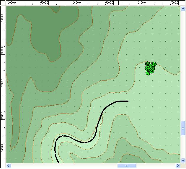
The actual view is shown in the map window:
The current editor mode is shown in this window:
 - pointing location.
 - panning the map.
- Ctrl + J - to get to cursor location.
Objects and areas selection
 - place or select/deselect objects and surfaces.
- Press-hold
 and move the mouse over the area - select it.
 - Ctrl +
 - including areas to the selected one.
 - ⇧ Shift +
 - excluding areas.
  on an object - select it.
- Ctrl +
 or press-hold the
  and drag a selection box around several objects - select them.
 - Press-hold Ctrl or ⇧ Shift, click
 on them and move the mouse up or down -rotate one or several selected object(s), .
Basic Map Processing
Detailed tutorial describing basic map making process can be found in Visitor 3: Making of simple landscape.
Getting started:
- Create new project: Project > New (Ctrl + N)
- In Project parameters box > Terrain size field: set Terrain grid size and Terrain cell size.
- Set project preferences ( Tools > Project preferences... ), fill in PathToMap\data to Folder - Textures field.
- To insert objects or roads, you will first need to define them in their respective lists accessible in Tool menu: Natural Objects, Artificial objects, Roads etc.
- To import surface textures, use Tools > Import Satellite&Mask (for detailed info on the subject see Making Satellite Texture and Mask and Layered Terrain Surface Representation).
To export your map:
- Open realtime viewer (Project > Connect to Buldozer, Ctrl + F7). Realtime viewer has to be running when exporting .WRP file.
- To export your map for the engine, select Project > Export world..., and store it to YourMap\YourMap.wrp. YourMap.hpp is stored in the same location, containing reference of keypoints (elements of 2D map).
Tools
Textures
ArmA
In new engine, surface textures are not controlled from the toolbox. Instead of groups of texture squares, surfaces are composed from several layers, as described in Layered Terrain Surface Representation, main input are:
- satellite texture (PNG) - equivalent of aerial photo
- surface mask (PNG, discrete colours)
- layers.cfg - definition of surfaces contained in the surface mask, based on their RGB values
These data are imported using Import satellite & mask option in Tools menu. This causes deleting of all previous surface definitions, segments of satellite texture and mask are generated to folder specified in Project Preferences as Textures folder.
In toolbox, there is only definition of texture layer size, which can be edited by ![]() on its name in the list.
on its name in the list.
OFP
This describes how surfaces were edited in older version of engine (Operation Flashpoint). Terraintextures and surfaces definitions (the final terrain properties are made in the config).
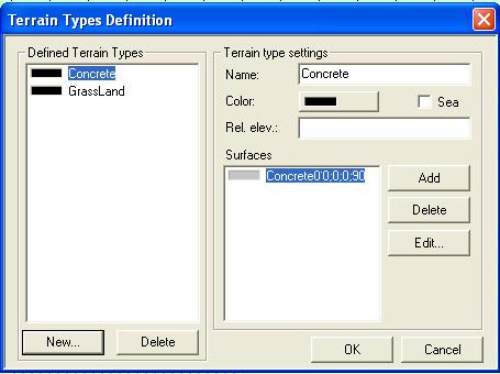
All surfaces/terrain surface definitions are made here. Visitor works with 2 types of textures: main textures (Primary and variants textures) and transisition textures. While you have to provide the first type, transition textures are created by Visitor to blend the transitions from one texture to another.
- "New...": Define a new terrain type.
- "Add": Add a surface type to a terrain type.
- Disable transitions on surface: Forces Visitor to create no transition textures between different terraintextures.
- "Select": Select primary texture. Note that you have to keep the name under 20 characters, so delete long paths from the name. Also keep in mind that the path is a relative path, so you have to force a folder stucture similar to the OFP2 structure.
- "Add": Adds variant textures. Here aswell a maximum of 20 characters in named are allowed.
- Occuran: Chance in percent that this variant of a texture is selected.
Natural Objects
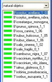
All vegetation is defined in the Nature Objects Definition box. You can use Natural objects filter button in main toolbar to hide or unhide them.
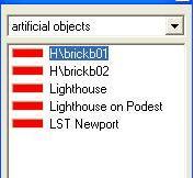
Artificial Objects
All artificial objects are defined in the Artificial Objects Definition box. Artificial objects filter button can be used to hide or unhide them.
Values of adjustments
- "Add": Add an object, browse the opening list to select the model you want to use.
NOTE: the maximum length of the name - 50 characters.
- Randomize size intervall: Model size will be randomly set in the given interval.
- Randomize angle interval: Model angle will be randomly set in the given interval.
- Randomize orientation interval: Model facing direction will be randomly set in the given interval.
Randomness happens as well during insertion objects placed by a script.
Roads
Road types and road sections are defined here. Each road consists of curved parts and straight parts with standard dimensions. For each road, curved and straight parts should be defined, as well as terminator segments (6.25 m segment with fading texture). Crossroads are special cases which need to have suitable road types defined for each of their ending direction.
- To start new road,
 on the map when Road network is selected in the toolbox. New key segment is created (any segment may become key segment) and road can be edited for every available direction (ending - one direction, curves and straight parts - two directions, crossroads - 3-4 directions).
 - To edit existing road,
 on it to access main editing dialogue.
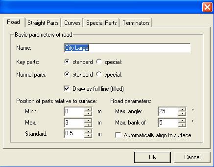
After hitting "Add" or "Edit" the Main setting window for the road shows up.
- Road: Main settings for given road type.
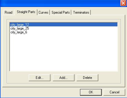
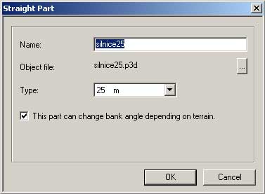
- Straight Parts: all straight sections of this road type.
NOTE: those parts need a certain length: 6.25, 12.5 or 25 meters.
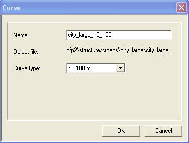
- Curves: all curved section of this road type.
NOTE: those parts need a certain radius: 25, 50, 75 or 100 meters.
- Special Parts: sections with a T-shape.
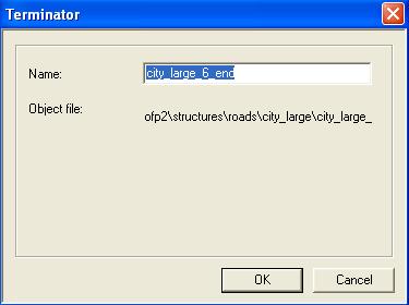
- Terminators: Sections that ends a road.
Project Preferences
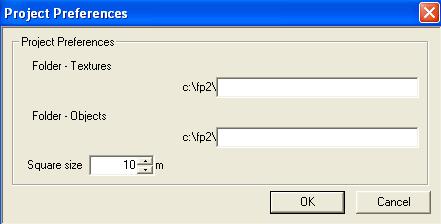
Paths to textures and objects (if stored in a specific place) and other project specific settings.
- Folder - Textures: Path to the folder where all lanscape textures are stored.
NOTE: the path is relative in the map, so you have to maintain the folder structure.
- Folder - Objects: Path to the folder where all objects are stored. This path is relative.
- Square Size: the side length of the square in game.
Project Parameters
Project parameters contain basic information about the project size. Most information is edited when project is started, later only Satellite grid and Texture layers dialogues are accessible.
Object Manager
There are only two functions.
NOTE: Visitor MUST NOT be connected to realtime viewer when using these functions.
If size of resolution LOD or Geometry LOD of a custom model changed, these functions are useful to give Visitor updated object description or to fix object shifts in vertical axis, including recalculation of all objects to relative elevation to surface =0.
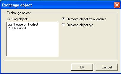
Exchange Objects
Deletes or replaces all instances of an object (models) from the map.
Snap Objects
Closes small gaps that can occur when placing objects like fences, walls.
NOTE: objects need to be prepared for snapping.
Editing Modes [F1-F10]
Artificial Objects [F1]
Placing artificial objects, except roads.
Select an object and click LMB on the map where you want to place it.
Natural Objects [F2]
Placing natural objects, except forest.
Select an object and click LMB on the map where you want to place it.
New road objects [F3]
list of new roads.
Road networks [F4]
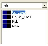
Placing roads.
Select a road type and click LMB on the map where you want to place it. A dialog will appear leading you through the placement process.
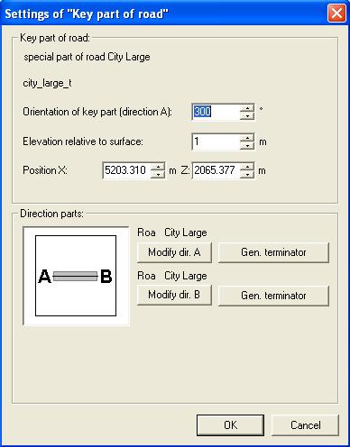
NOTE: You only have to place the first key part of a road section. Then you can simply click LMB on the map and Visitor will try to reach the point automatically. You can do it manually. If you click LMB on a placed road, the road property window will appear.
Every road part, except terminators, have two main directions: A and B, reflecting both ends of key section. Visitor uses the closest end of a road to reach a point on the map.
- Orientation Of Key Part (Direction A): Direction the A end is facing, angles are only possible in 10°/step.
- Position X and Position Z: position of the key part on the map.
- Gen.Terminator: Create Terminator or new Key section at the end of direction
- Modify Dir. A:
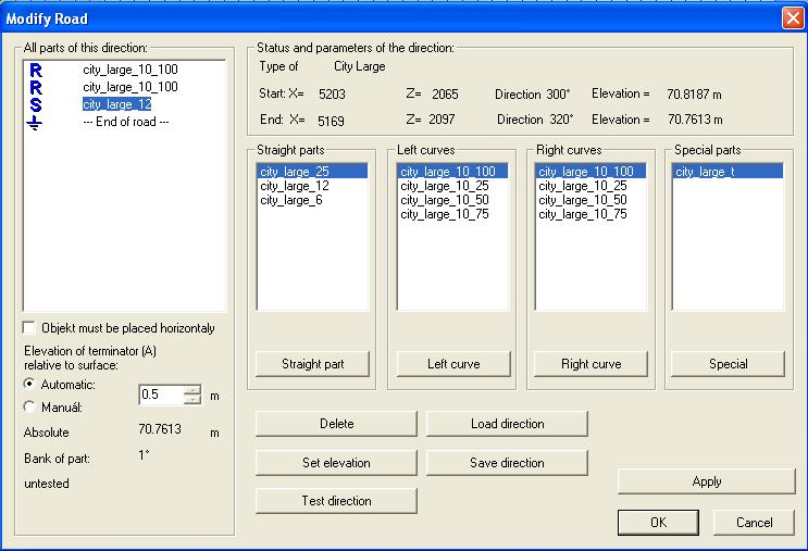
Note: Deleting or Adding a part in the middle of the road changes the rest of the road. Added sections will be inserted before the section marked in "All Parts Of This Direction".
- All Parts Of This Direction: All sections from the key section to the end of the road
- Delete: Delete selected section.
- Straight Part: Adds the selected straight part to the road.
- Left Curve: Adds the selected left curve section to the road.
- Right Curve: Adds the selected right curve section to the road.
- Special: Adds the selected special section to the road.
Key points [F5]
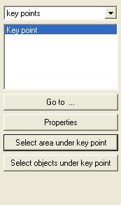
Display/Create key points. List of all key points on the map. To add key points, click LMB on the map in this editing mode.
Same options as in [[#Named Zones [F6]]] editing mode.
Terrain vertices [F6]
Landscape height changing. Landscape forming tool.
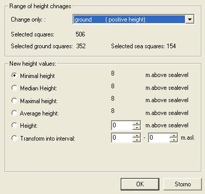
Change Height: Changes the height of points/area on the map.
- Change only: Shows only up when the selection has sea and land points.
Ground (Positive Height): Only points over sealevel will be changed.
Sea (Negative Height): Only points below sealevel will be changed.
- Minimal Height: All points will set to the height of the lowest point of selection.
- Median Height: All points will set to the median height of selection.
- Maximal Height: All points will set to the height of the highest point of selection.
- Averange Height: All points will set to the averange height of selection.
- Height: All points will set to this height.
- Transform Into Intervall: Takes the current height profile of selection and stretches it into the given intervall.
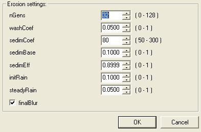
Erosion: Erodes Landscape.
- nGens: Number of generations of erosion (max. 128 generations).
- WashCoef: Wash Coeficiant, how strong does water flow affect terrain.
- SedimCoef: Sediment Coeficiant, how fast sediments sink down and stay where they are.
- SedimBase: Sediment Base, how much sediment is there from the beginning.
- SedimEff: Sediment Effect, "wash out" resistance of terrain.
- Initrain: Strenght of rain.
- SteadyRain: How long does the rain last.
- FinalBlur: Creates a smoother surface.
Background images [F7]
Sets a background picture as reference.
NOTE: only .bmp format are supported.
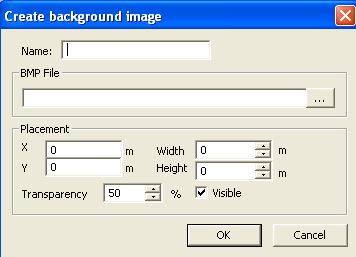
To see the background image, in the "Create background image" dialogue (below), first choose some BMP file. Placement values are coordinates for top left corner (for the image covering whole map, set both to 0). Width and Height are true sizes of imported image. Example: If the map is e.g. 10240x10240 meters and the background image covers whole area, set Width and Height values to 10240. Smaller hi-res images can be used as well, if the coordinates and size are set correctly.
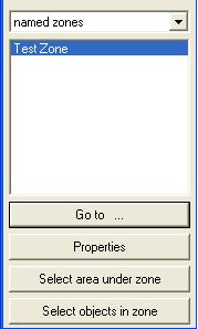
Named zones [F8]
Display/Create named zones.
List of all named zones on the map. To name a zone click LMB on map screen the selection box.
- Go To...: Centers view on selected zone.
- Properties: Opens properties window (same as doubleclicking the selection).
- Select area under zone:
- Select Objects In Zone: Selects all objects that are in this zone.
...
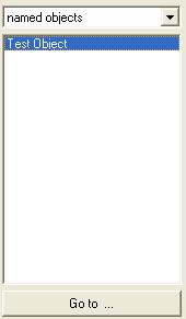
Named objects [F9]
Browser for all named objects on the map.
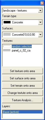
Surfaces (OFP) [F10]
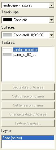
Sets textures/properties to surfaces.
- Terrain type: Current selected terrain type.
- Surfaces: Current selected surface.
- Textures: Current selected texture, if set to "random selection" it will randomly choose on of the available textures.
- Set Texture Onto Area: Set current texture on selected area.
- Set Surface Onto Area: Set current surface on selected area. The textures are set according to their probabilities.
- Set Terrain Onto Area: Set current terrain on selected area. The surfaces are set according to their definition. Same for the textures.
- Change Texture Onto Area: Changes texture in area to current selected texture.
- Texture Analysis..:
Woods [F11]
Creating forests as they were in Operation Flashpoint maps. Obsolete and kept only for backwards compatibility.
Terrain
You have several options to edit the height profile of your map:
- Manually ("Landscape - Vertexes" as editor mode/F9): This is the most work intensive version, you change all landscape point individually. We recommend to use this method only for finetune a map.
- Import ASE Height Map (Projects/Import Terrain): Read in an 3D Studio Max .ase height map. This will be more likely removed in future.
- Import PNG Image (Projects/Import from Picture): Imports 8 or 16 bit PNG image, a PBL config must be present (it's created automatically when you export PNG file in the same location). PBL file example:
class cfg
{
	PNGfilename="world.png";
	squareSize=5.000000;
	originX=0;
	originY=0;
	minHeight=120.000000;
	maxHeight=735.000000;
};
- Import from XYZ map (Projects/Open "Files of type: *.xyz"): XYZ is ASCI file format contaiting space delimited X Y Z on each line, where XY is UTM and Z is in meters. During import you can align data to top or bottom left and set target data dimension to crop data or extend area.
- Inside Buldozer: You can use U (small step up), I (big step up), J (small step down) and K (big step down). This is also best used for finetune the profile.
NOTE: for import terain operations (and any other large scale operations like this) it is recommended to disonnect Buldozer otherwise it takes really long time to process the map.
Scripts
Visitor 3 gives you the opportunity to use scripts for certain tasks. Scriptfiles have the ending .vis. We use the OFP own scripting language with some extensions. For all possible command see the Visitor Script Command Reference For some examples see Script folder in the directory you found this HTML file.
DEM Files Manipulation and Export
Visitor 3 can't import of DEM files but you can easily convert DEM files to XYZ files using 3rd party software. First choice for this task is MicroDEM. How to export DEM to XYZ from Microdem 6.03:
- Start Quickview application from Microdem folder.
- Select File -> Data Manipulation to open Data Manipulation window (or alternatively click at In<->OutIcon in the Microdem's toolbar). Note that you must select this mode before you do any other actions in Microdem, otherwise it is disabled.
- In Data Manipulation window select Export -> ASCII XYZ, full DEM, open DEM file you want to export and select XYZ file. You're promted to ask coordinates units, use UTM for XY and meters for Z.
Tips and tricks: Another good and freely available DEM utility is 3dem. It's more user friendly and faster than MicroDEM in many operations. The fastest and most compatible file format to use to transfer files from 3dem to Microdem is GeoTiff. Here are some of tips and tricks how to process DEM data using 3dem and Microdem to prepare them for Visitor:
- Patch missing DEM data to avoid holes in the map: Operation -> Patch missing data in 3dem; Edit -> Fill DEM holes in Microdem Data Manipulation.
- Resample DEM to desired size and resolution: In Microdem Data Manipulation Resample - DEM, change X, Y spacing from current value to desired value
- Merge DEMs: In 3dem just open multiple DEM files at the same time to merge them; in Microdem Datamanipulation select Merge -> DEMs, consequently open DEM files you want to merge, press cancel in Open merging file selector after last DEM is added and fill the target file name in merged DEM file selector.
- Crop DEM: In 3dem, use Operation -> Select Smaller Area, select the area and press Enter; in Microdem Data Manipulation use Subset -> DEM rectangle and select the method you prefer.
Advanced Surface Editing
Layered Terrain Surface Representation
Your Old Flashpoint Map Project to Arma Map Project By Ivan
To avoid conflicts arising from simultaneous use of old and new projects in V3, the idea is to have a clone of the old project and transferring there old content using scripts. Since Visitor works with VISITOR OBJECT NAMES, not with MODEL NAMES, it makes the task easy. Keep old project untouched as reference and source for exporting content. Tutorial is based on assumption that you have p:\ as virtual working drive.
Make Target Project
You will need to make project with same dimensions as old OFP map. - Make new project in Visitor. - Specify width/height: 12800 m. Square size is 50 m.
Project Preferences
Let's set paths to objects and correct satellite grid number. For Arma maps, we use following settings in Project Preferences: Textures folder: p:\ca\abel\data Objects folder: p:\ (We can use all objects from all available PBOs this way, you will be able to use Arma objects this way). Square size: should be 50 meters in your case Satellite grid: Calculate proper number using the tutorial Layered Terrain Surface Representation, OpenOffice table or updated version of V3. The goal is to enter correct number so that Visitor will cut imported HUGE texture into 512x512 bits. 512x512 is important, it is best choice for good performance. I used value 16 for Abel, "satellite" texture size was 6400x6400 px.
Detail Texture Resolution Setting
You need to set proper size of area, on which detail textures will be mapped. On Arma islands, we use 40 meters, all textures are made in order to fit to this size. You will probably need to tweak size of original textures to fit your map's values. Clutter density values can be updated accordingly. - Make sure you have Panel of Objects visible (set in View menu). In Panel of Objects, choose "landscape-textures" from first roll-down menu. - On the bottom of panel, there is Layers space, there should be one line. RMB on it and choose to Edit layer. - Name of layer is not important. Name it as you wish. - Resolution IS important. Note that available values are ([terrain size]*2expN). For big maps, you may use quite big number (~100-200 meters, ugly look guaranteed). For Abel, I chose 50x50 meters. Using Sahrani surfaces as they are will thus make them look 1.25x bigger, they stretch on surface 25% bigger than on Sahrani.
Objects
Transferring objects is not a big issue. You just need to name new object in new project EXACTLY SAME as in old one. Then you may use two ways of inserting objects. - E.g. there is object "kostelik" (=little church) in old project. Path to model is ..\Data3d\kostelik.p3d. In new project, make object with same visitor name, updated Arma counterpart is ..\ca\buildings\kostelik.p3d - Now the first way of copying it, quite suitable for copying vegetation because it saves relative size of object: Select objects of this kind in old project, copy them (Ctrl + C). In new project, go to "Edit"-> "Paste absolute" (or ⇧ Shift + V) and objects should be copied on their exact locations. - Second way is script way: We made ExportObjects and ImportObjects scripts, which are part of V3 distribution. You may add them to menu by going to "Scripts"->"Manage scripts", then add them from your Visitor3\Scripts. They are ExportObjects_100.vis and ImportObjects_100.vis. Now you can export data from old project (use default settings, specify path to *.txt file) and import them into new one.
Forests
You can forget about old forests. My suggestion is to either compose forest square mock-up and copy it or make new ones.
Roads
Same thing as 4. You will need to define all road parts in the same way as in original project. Then you just copy them and Paste-Absolute them into new one. Correct counterparts should be selected.
