Car Creation – Arma Reforger
Goals of this tutorial
In this tutorial you will learn about:
- Importing your first FBX file
- Adding sockets & skeleton
- How to configure new car
Adding new car
Overview
Preparation phase consist of things like:
- Preparing basic structure
- Preparing mesh
- Exporting mesh
Preparing structure
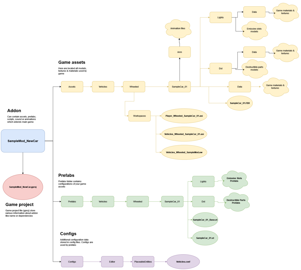
While keeping to official structure is not mandatory and there are no engine restrictions asset wise about it, it's recommended to follow guidelines listed here - Data (file) structure - to ensure that all automation plugins are parsing your assets correctly and make it later easy to navigate.
Below is recommended structure of addon which contains a new car asset
Preparing mesh
Model orientation
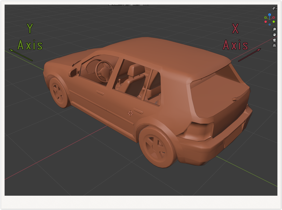
One of the most important thing to begin with is making sure that your model is properly orientated. Similar to weapons, there is one important rule to keep in mind
That means, when you are importing A3 weapon you need to rotate it by 90 degrees to the left!
Splitting mesh into parts
In principle, following elements of the vehicle should be split to separate models
- Vehicle accessories (i.e. vehicle roof) used for creation of variants of the same vehicle like i.e. cargo or fuel variant of the same truck.
- Destructible elements (windows, breakable elements of the vehicle, etc)
- Emissive lights
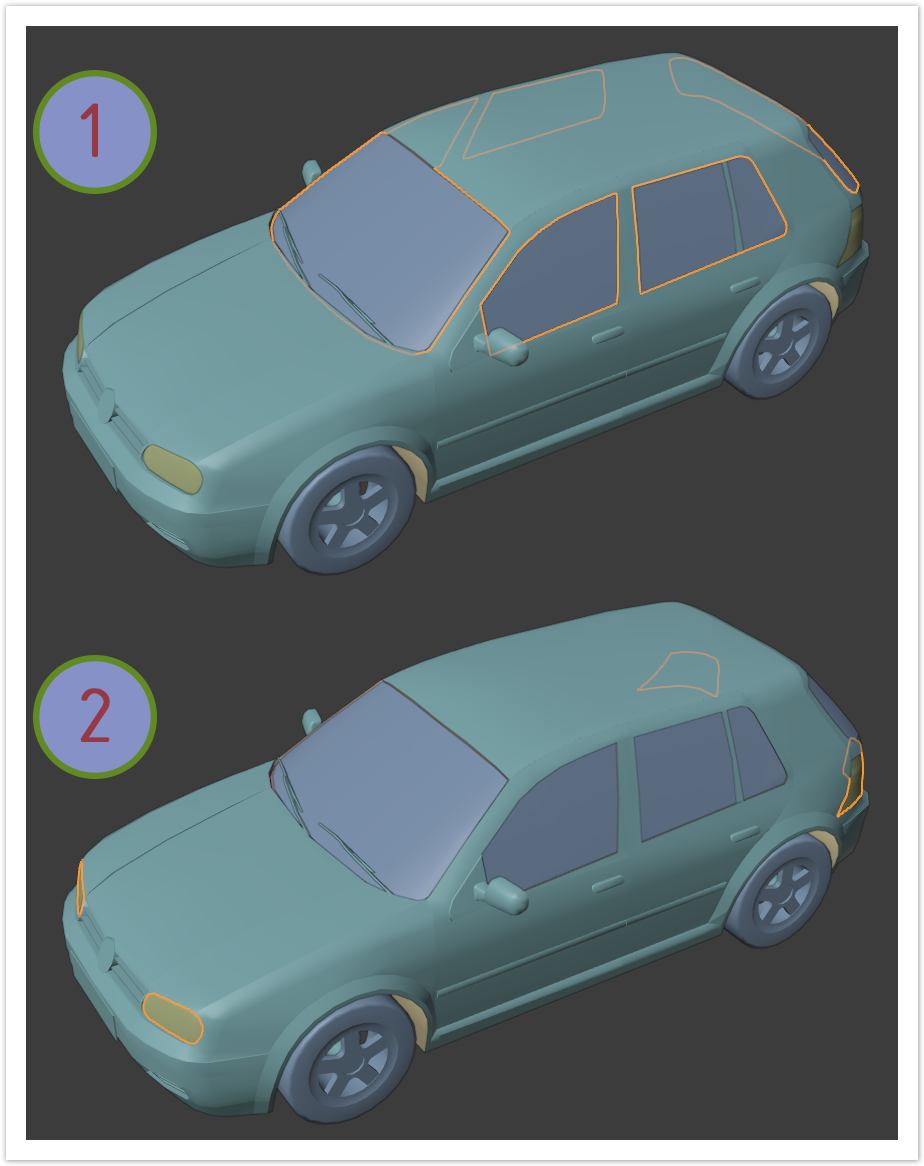
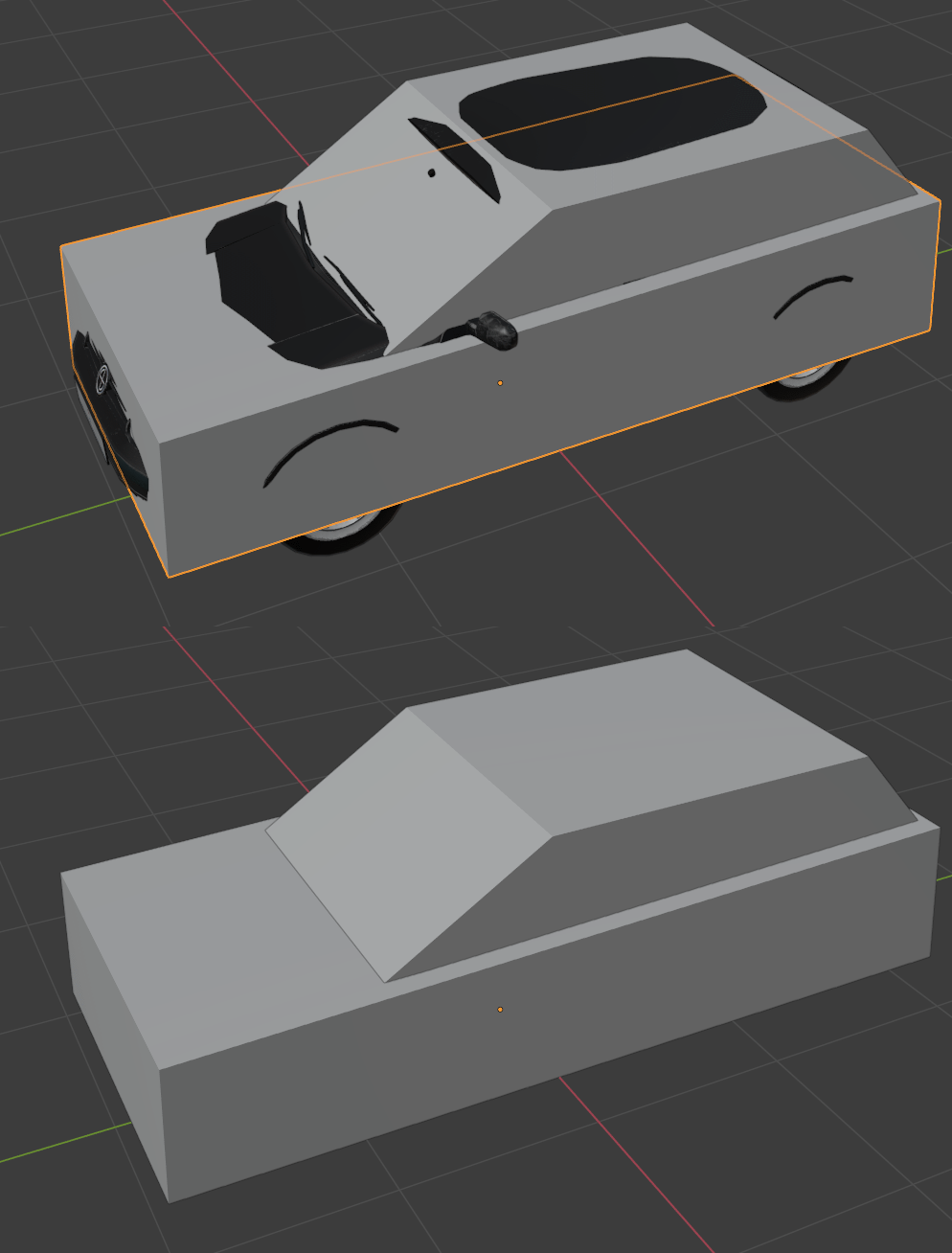
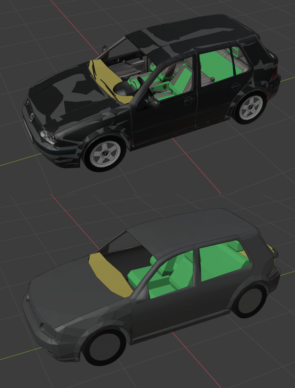
In this example, windows (1) & emissive lights (2) were separated to their own FBX files.
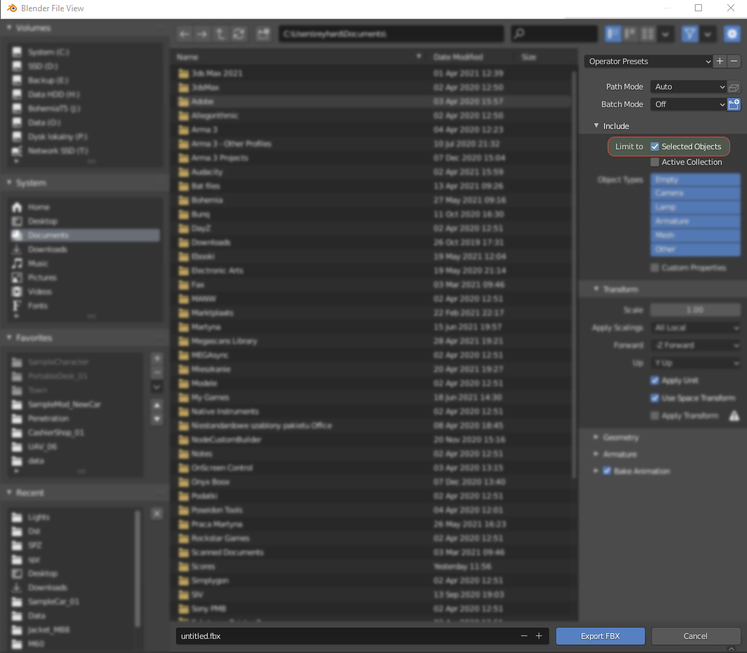
If those elements are already separated to unique objects, then it's possible to select them one by one and save them as FBX file with export limited to currently selected object.
Generally, such simple objects doesn't require skeleton but in case of more complicated elements (like gun mount), it's possible to add them to mesh.
Naming of objects
When it comes to naming, there are few important rules to keep in mind.
- _LODx suffix is used to indicate Level of Details. You can have up to 8 LODs.
- UBX_, UCX_, USP_, UCS_, UCL_, UTM_ prefixes are used to mark Colliders (Box, Cylinder, Sphere, Capsule, Cylinder, and Trimesh respectively)
- OCC_ prefix is used for Geometry Occluders
- COM_ prefix is used to determine geometry center of mass
There are also some general guidelines regarding naming of the vehicle parts on Vehicle Pipeline - Parts page. It's strongly recommended to follow those rules since most of the base prefabs are using those names by default to reduce duplication & make easier data management. On that page, there are also general guidelines regarding naming objects which are not explicitly mentioned there.
Vehicle can also have various small sockets for destruction, crew positions management and contextual actions. Some of the rules regarding slots naming can be found in slots section of Vehicle Pipeline page.
Creating colliders
Colliders are special type of objects which are used to calculate various kinds of collisions - be it physic simulation or tracing of bullet penetration. There are few rules regarding those colliders and most of them listed here - FBX Import - Collider usage. In case of models imported from Arma 3, there are usually some convex components already present which could be used a base for collision geometry. It's recommended though to make at least fire geometries from scratch.
In case imported convex components are useless (too complex collision geometry or not detailed enough fire geometry) and completely new geometries have to be created, below there are some tips & rules.
Collision geometry
This type of geometry should be kept as simple as possible and amount of colliders should be also kept low. Simple type of colliders like convex, cylinders or cubes should be used. Large single shapes should be used to avoid issues with collision imprecision.
Fire geometry
Penetration geometries can be bit more detailed and, in contrast to Real Virtuality engine, they don't have be convex. Usage of trimesh geometry can greatly speed up creation of detailed fire geometry.
 Some additional informations can be also found on Vehicles - Colliders and Fire Geometry.
Layer presets
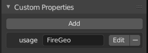
Layer presets are used by engine to determine how given collider should behave when it collides with other object.. Layer Presets can be either directly defined in modelling software by adding custom property to object or can be changed in Workbench after successful import of the mesh. If you are using Blender, there is small official tool - Enfusion Blender Tools - to assist you with assigning correct game materials & layer presets on colliders.
For creating custom attributes in 3dsMax, use only the Parameter editor in Animation menu, otherwise the properties in exported FBX can't be edited in Maya. So doing it with Object Properties/User defined is FORBIDDEN
More details about Collision Layers, Layer Presets and Interaction Matrix can be found on linked page.
Setting skeleton & rigging mesh
When creating skinned objects, Enfusion Workbench expects that the whole object is skinned to some bone. Otherwise importer will try to "fix" it by skinning remaining faces to some root bone. Otherwise, you might see following error in the console:
RESOURCES (W): Missing some mesh skinning weights (Object_LOD0). Weighting them to root
In Blender realms, this means that any object with Armature modifier, must be fully skinned to some existing bone through vertex groups.
If you have some animated collider please keep in mind that only trimesh colliders can be skinned. In all other cases you have to use 100% weight.
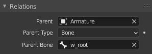
In Blender it gets even bit more tricky and Object Relations (in Object tab) have to be used.
FBX export settings
Most of the general rules can be found on this page this page . In principle, when export from i.e. 3DS Max, you have to make sure that you are exporting in binary format in version 2014/2015. Furthermore, Triangulation & Preserve Edge Orientation should be turned off.
Blender wise, there are 3 most important things to keep in mind when exporting FBX
Importing Mesh
Overview
In this chapter following topics will be explained
- Importing new model
- Importing textures
Importing & registering new model
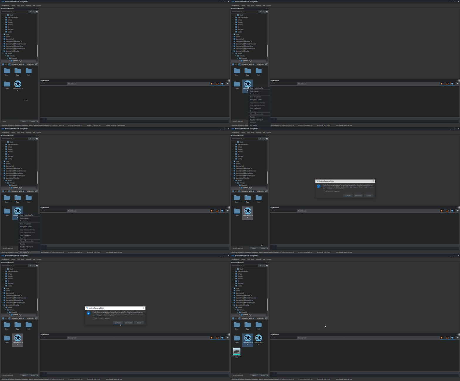
Once mesh was successfully prepared and all selections, sockets & snap points are in place, it's time to try our asset in game. Majority of the process is already pretty well described on FBX import - Import process in the Workbench page.
In principle, all you have to do is click with right mouse button on your FBX files and select from context menu Register and Import option and then click as Model to import selected mesh as a game model.
Checking colliders & materials
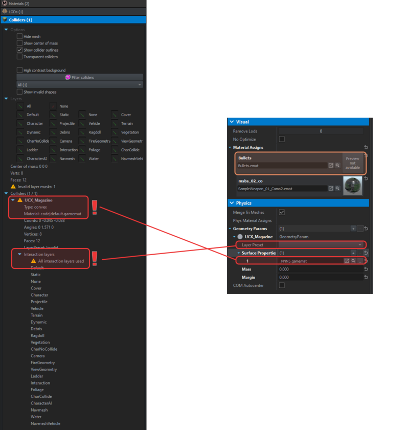
After initial import was done it's time to make sure that materials & colliders are using proper materials & colliders. By default, Enfusion will try to assign material based on the name of the assigned texture in mesh. If it fails to find such texture, new dummy material (see area marked in orange on screen below) will be created in data folder next to the FBX model.
There are 2 typical errors when it comes to collider configuration:
Skeleton & hierarchy
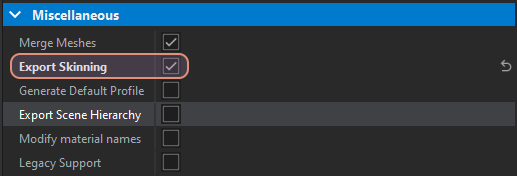
Since this model is animated, it's very important to check Export Skinning checkbox in Import Settings of model. Without that parameter selected, vehicle will be imported without skinning or any sockets!
Importing textures
In principle, you can use same procedures as the ones described in |Weapon Modding - New Materials creation page. By default, Workbench will new materials based on the materials name from the FBX file.
Adding basic car configuration
Overview
Following topics will be covered in this paragraph
- Creation of new car
- Configuration of actions
- Configuration of crew
- Basics of wheeled simulation
- How to change engine parameters
- Changing of driving characteristics
Creating new prefab
When creating new vehicle, it's recommended to use one of the core vehicle prefabs located in Prefabs\Vehicles\Core. This way, most of the crucial components will be already present in new car prefab with already some of the parameters filled in.
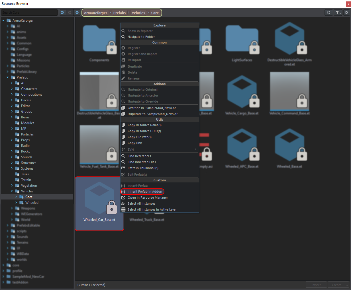
Since this asset is a car, Wheeled_Car_Base.et is going to be used as base. Easiest way to do so is using Resource Browser attached to World Editor ( it's not going to work in Resource Manager!) - after navigating to Prefabs\Vehicles\Core, click on Wheeled_Car_Base.et with Right Mouse Button and select from context menu "Inherit Prefab in Addon" option. After selecting name of new prefab, the only thing left to do is moving prefab that prefab to more appropriate folder in addon.
Other method involves duplicating some already existing prefab - this might be handy if you are creating something similar to already existing cars. For instance if you are making some car with 2 axis, you could use Duplicate in "addon name" function on UAZ469.et prefab and then start to adjust parameters of newly duplicated file.
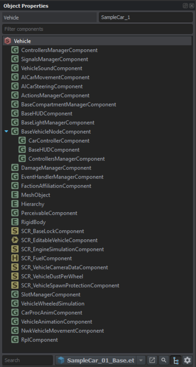
New SampleCar_01_Base.et prefab should already have almost all necessary components for adding new car to the game. Among missing components there are things like:
- SlotManagerComponent - this component is used to attach new elements to the vehicle like destructible parts (windows) or completely new elements (machine-gun mounts)
- VehicleSoundComponent - handles sounds that vehicle emits
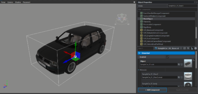
With that prefab already being present, it's possible to starting changing properties so new car is resembling newly imported mesh. To do so, MeshObject component has to be changed and SampleCar_01.xob need to be applied to Object field. As a result, SampleCar_01.xob mesh should be now visible in World Editor view port.
| Components list | MeshObject component with SampleCar_01.xob |
|
|
Creating actions
Actions Manager Component
Before even vehicle can be entered, it requires setting up actions so engine knows where to show certain options like get in dialog. Those actions are configured in ActionsManagerComponent.
In this component you can find Action Contexts, which serves as a library of actions (somewhat similar to memory LOD in RV engine but with additional layer of information attached to it) & Additional Actions. Usually contexts defined in this component are used by other components (like BaseCompartmentManagerComponent)
Each context defined in Action Contexts has option to change Context Name, Position, Radius & set if action is Omnidirectional. Position of the context can be either tied to bone in hierarchy or manually entered via gizmo controls. It is also possible to combine those two methods.
Allow Cross Hierarchy option is used when vehicle consist of multiple prefabs (attached via i.e. SlotManagerComponent) where it's desired to be able use actions from attached components.
Creating action contexts
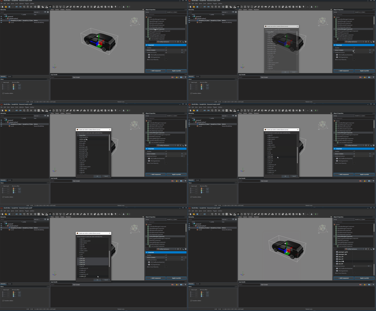
If vehicle has already some bones or sockets which could be used as position for action context, then it's possible to use Create user action context(s) from bones option which is available in context menu of ActionsManagerComponent. This menu can be invoked by clicking with Right Mouse Button on ActionsManagerComponent in components list.
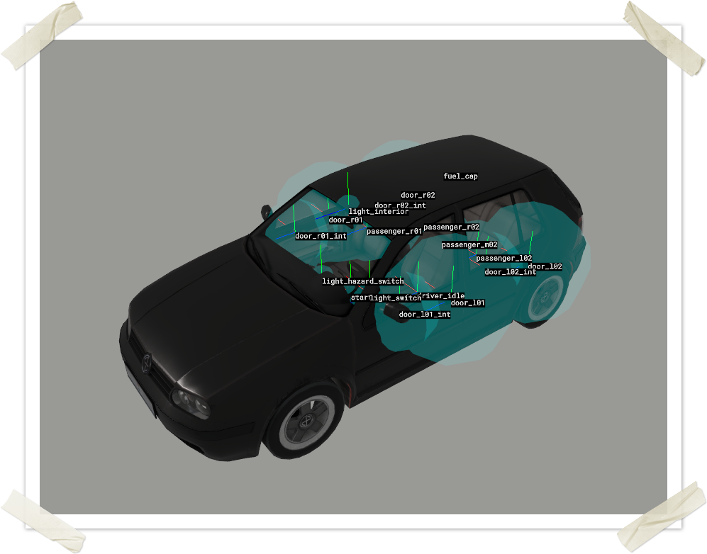
It's also worth to mention that this context menu has few other options, which are quite useful for setting up & debugging of context actions. Below you can see in action transform gizmos (activated via Toggle context(s) transform gizmo visualization ) and radius visualization (activated via Toggle context(s) radius visualization option).
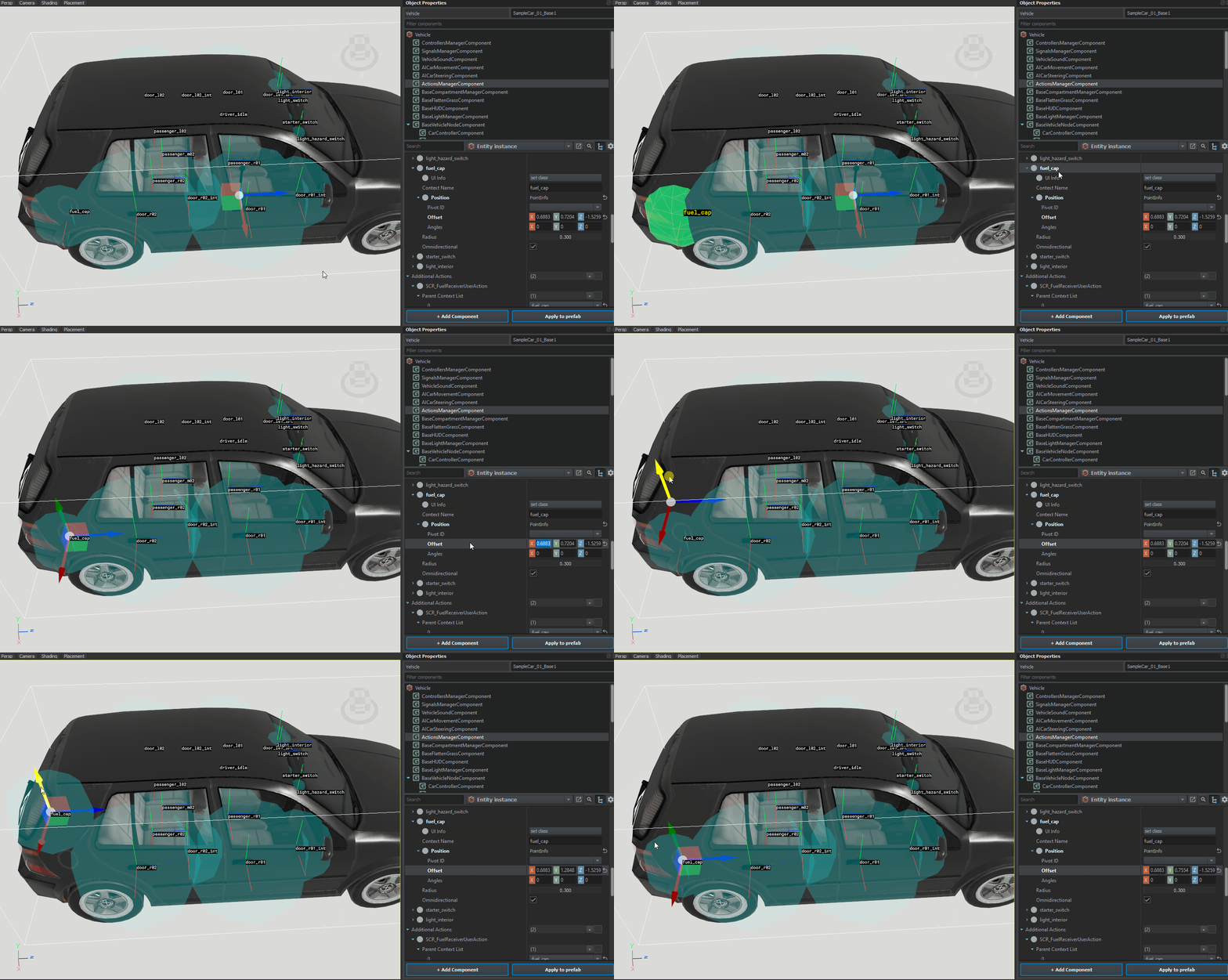
Position of Action Contexts can be also adjusted inside of the view port. To do so, click with Left Mouse Button on one of the Offset fields (X, Y or Z). After, transform gizmo should snap to existing offset and it should be possible to manipulate location of the action. It is also possible to use Pivot ID parameter which will snap action context to selected bone or pivot - this option is especially useful if it's desired that action follow the bone like on turrets.
For this particularly vehicle, following Action Contexts were created:
| Name of action context | Usage |
|---|---|
| door_l01 | Those action contexts will be used to determine position of get in action. Recommended to place at the middle of the door |
| door_r01 | |
| door_l02 | |
| door_r02 | |
| door_l01_int | Those action contexts will be used to determine position of get out action. Recommended to place at the middle of the door or door handle |
| door_r01_int | |
| door_l02_int | |
| door_r02_int | |
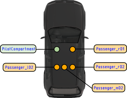
| driver_idle | Those action contexts will be used to determine position of switch seat action. Recommended to place at the middle of the seat |
| passenger_r01 | |
| passenger_l02 | |
| passenger_r02 | |
| passenger_m02 | |
| light_hazard_switch | Action context for switching hazard lights |
| fuel_cap | Action context for refuelling vehicle |
| starter_switch | Action context for engine start/stop - placed at the starter position |
| light_interior | Action context for toggling interior lighting |
Adding additional actions
Additional actions are type of actions which are not part of other components. Usually those actions are scripted and it's possible to add new ones. For purpose of this tutorial, 2 new actions will be added:
- SCR_EngineAction - adds action to toggle state of the engine. In this example starter_switch should be added to Parent Context List of that action
- SCR_FuelReceiverUserAction - adds action to refuel vehicle. In this example fuel_cap should be added to Parent Context List of that action
Compartments setup
Compartments are used to define who, where & how units can access seats in the vehicle. Most of the configuration is performed in BaseCompartmentManagerComponent, where compartment slots are defined itself, and in ActionsManagerComponent, which provides information about actions properties & their position.
Overview of compartments
By default, Wheeled_Car_Base.et prefab already contains PilotCompartment slot. This slot defines driver of the vehicle. Bunch of parameters should be already inherited from parent prefab (like UI infos containing strings for actions), yet some of the values still have to be filled in. Those parameters which need to be update include:
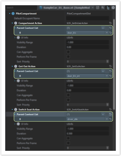
- Compartment Action, Get Out Action & Switch Seat Action – those define which action contexts are used for get in, get out or switch seat action & how it’s presented in game UI. Compartment Action (get in action) is available when player is outside of the vehicle and wants to, as name suggests, get inside. Get Out Action is present when player is seating on that slot. Finally, Switch Seat Action is available only when player is seating on some other seat in the same compartment of that vehicle and is looking at the action contexts defined by this action.
- Passenger Position Info – stores information about position of the character inside of the vehicle. (Similar to seat proxies in RV engine)
- Door Info List - contains information about actual get in & get out position & behavior. Here it is for instance possible to define if engine should play animation tied to the vehicle or if character should be instantly teleported in & out.
Making adjustments to those classes listed above should be enough to get first driver seat working in game. Rest of the properties are described in detail on Vehicle Compartments page.
Configuring compartments
Having knowledge about what PilotCompartment is, it’s time to start setting it up. In Compartment Action, Get Out Action & Switch Seat Action main thing to do is adding parent contexts to Parent Context List. Now it’s proper moment to use action contexts created in previous step. In this example, following contexts will be used:
- Compartment Action -> door_l01
- Get Out Action -> door_l01_int
- Switch Seat Action -> driver_idle
In case slot action can be performed from multiple sides (i.e. middle car seat – this one should be accessible from both left & right side), it is possible to define multiple contexts.
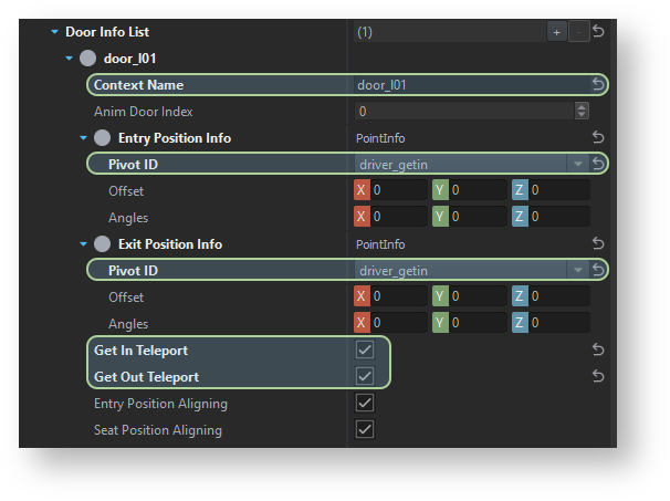
Next step on the way to fully functional car is configuration of Door Info List. In this class, contexts provided in Compartment & Get out Actions are linked to respective doors, so engine know where character should get out or which door should be animated during get in action.
In this example there are no actual get in or get out animations and simple teleport is used. To activate such behavior, Get In Teleport & Get Out Teleport should be checked.
Next step will be changing get in location in Entry Position Info. In this class it is possible to either define offset & angles manually or use one of the existing sockets present in the model. In this example Pivot ID is used & changed to driver_getin socket.
By default, Wheel_Car_Base prefab doesn’t have Exit Position Info class present, so it has to be created by clicking with Left Mouse Button on set class button. Once class is there, similar steps to Entry Position Info class can be applied – in this case it will be changing Pivot ID also to driver_getin socket.
Once those steps are completed, it should be possible to get in & out from the vehicle. In both cases character will get in & get out at driver_getin socket location.
Adding new compartments slots
New compartments slots can be created in two ways:
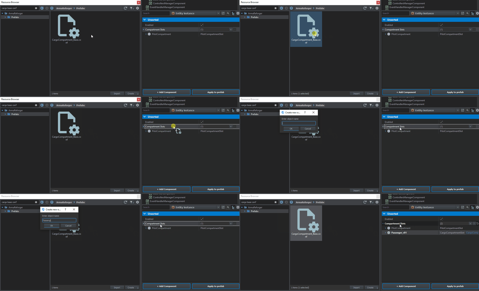
- By drag & dropping one of the existing Compartment Slots configs (basic one are located in Prefabs/Vehicles/Core/Configs) – this way some of the common parameters will be already inherited from selected config. When doing multiple seats of same type specific to some asset (i.e. Ural-4320 rear cargo seats), it is also recommended to create new, inherited config (conf inherits from CargoCompartment_Base.conf ) which is then applied to such prefab.
- By clicking on arrow icon on the right side of the Compartment Slots – this will create new class of your choice with only default values.
Both of the methods are described in detail on Vehicle Compartments page. In most cases, it is recommended to use config solution, since it makes easier maintenance of such prefabs.
In this example, 4 additional cargo seats will be added to the vehicle using CargoCompartment_Base.conf as a base.
Vanilla content is using following naming convention for passenger seats:
- Passenger_ - prefix indicating type of the seat
- _r_ - indicates whether seat side - left (_l_), right (_r_) or middle (_m_)
- 01 - row indicator - counting from front of the vehicle.
To add new Cargo Compartment Slot, locate CargoCompartment_Base.conf in Resource Browser and then drag and drop it on Compartments Slots property.
After that, similar to Pilot Compartment, it is necessary to fill in:
- Parent Action Contexts for Compartment Action, Get Out Action & Switch Seat Action
- Select Pivot ID or adjust offset in Passenger Position Info
- Adjust data in Door Info List
Passenger_m02 is sort of special case since it is desired to be able to access that seat from both left & right side. To do so, it is necessary to two contexts to Compartment Action Parent Contexts List & then, create two entries in Door Info List where both contexts matches with those newly created entries.
Simulation setup
Simulation for vehicles like cars, trucks or wheeled APCs is stored in VehicleWheeledComponent. This component holds information about configuration of engine, gearbox, suspension or wheels. More details regarding all available parameters in this component can be found on Vehicles - Wheeled Simulation page.
Engine parameters
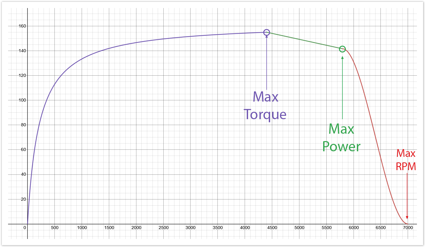
When setting up engine parameters, it is possible to use real life values. Usually it's not that hard to find information about power & torque of engine with RPM data attached to it. Below is table containing example source data which will be used to configure vehicle in Workbench
| Engine | Power | Torque |
| I4 16V | 86 kW at 5,800 rpm | 155 N⋅m at 4,400 rpm |
Using that data, it is possible to fill following data in Engine section of VehicleWheeledComponent
- Max Power - 85 kW
- Max Torque - 155 N*m
- Rpm Max Power - 5800 rpm
- Rpm Max Torque - 4400 rpm
Below is visualization of data https://www.desmos.com/calculator/j63rwoyvnh
Inertia parameter controls engine moment of inertia. In layman's term, it affects how fast engine gains or lose rpm. High inertia results in slower gain of rpm's but it also means that less rpm will be lost during i.e. changing of gears or when releasing thrust. Table below can be used as sort of guidance but it is still recommended to experiment with that value and tweak it till reaches desired state
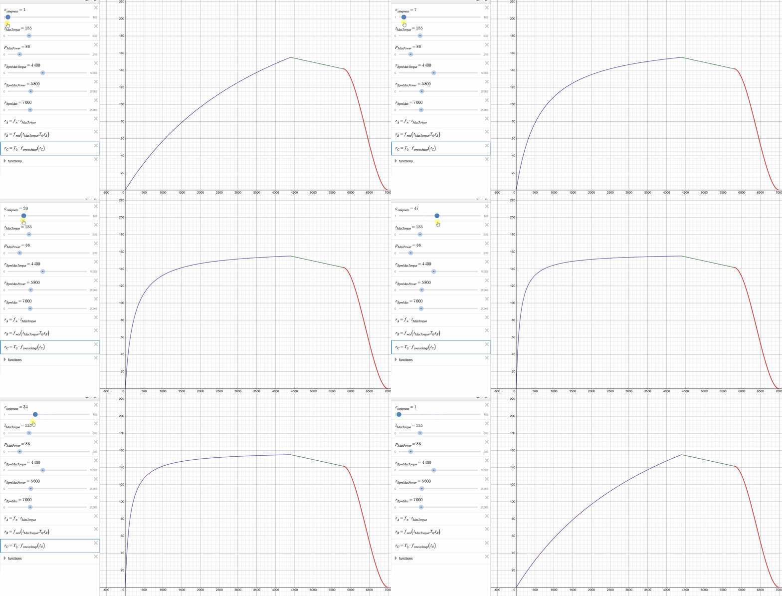
Steepness parameter controls how fast engine can reach max torque. This parameter can be used to i.e. reduce the acceleration of the vehicle or to fine tune torque/rpm graph. Effect of that parameter can be observed below
Rest of the RPM parameters, like Rpm Idle, Min Clutch, Redline & Max, can be also directly copied from source data if its available. In this example, following data was used
- Rpm Idle - 850 rpm
- Rpm Min - 600 rpm
- Rpm Clutch - 1500 rpm
- Rpm Redline - 6500 rpm
- Rpm Max - 7000 rpm
Last but not least, there is Output parameter, which controls where power produced by the engine is transferred. In this example Clutch is used as a Output.
Gearbox & Clutch parameters
In Clutch section of the VehicleWheeledSimulation component there are two parameters available. Clutch Output should be kept to Gearbox & Max Clutch Torque - parameter controlling maximum torque that clutch can provide - should be tweaked. 1.6 * Max Torque can be a good starting point.
In Gearbox section gear that can be filled in. In this example, following data was used as source
| Final drive | 68 : 16 = 4.250 |
|---|---|
| 1st gear | 38 : 11 = 3.455 |
| 2nd gear | 35 : 18 = 1.944 |
| 3rd gear | 37 : 27 = 1.370 |
| 4th gear | 32 : 31 = 1.032 |
| 5th gear | 34 : 40 = 0.850 |
| Reverse gear | 38 : 12 = 3.167 |
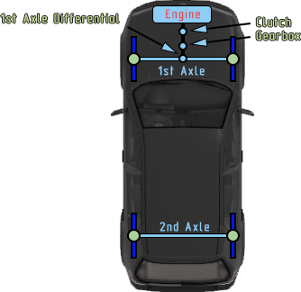
Forward parameter contains array of forward gears. New gears can be simply added by clicking on plus sign + on the right side of the parameter. Reverse parameter is used for reverse gear. Final drive is defined later in differential which is defined in one of the Axles. Depending on the configuration of the vehicle, it is possible to do various types of drive trains. In this example car is using simple forward wheels drive.
Suspension parameters
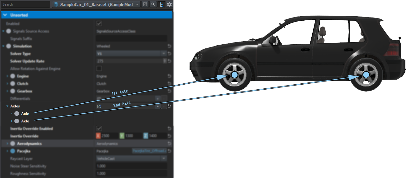
One of the most important part of the vehicle configuration is setting Axles & their Suspension values. First, it is necessary to add as many Axles as vehicle has. This can be done by clicking on plus + sign on the right side of the Axles property.
Wheels parameters
Each vehicle, whether it be FWD, RWD, AWD, or 4WD will have at least one differential on the drive axle. For each drive axle, choose the appropriate Type (Closed, Open, or Limited Slip Differential) and the Ratio of the differential's gear reduction.
- Open differentials will split torque evenly when both tires will have equal traction, but will send all torque to a tire which loses traction. This is not ideal off road, but is the most common consumer car differential.
- Locked differentials will ensure both wheels on an axle always rotate at the same speed. This provides great grip but is not ideal for turns, where wheels are meant to rotate at different speeds.
- LSDs are not locked but will increase grip between the wheels if one wheel loses traction. This provides a compromise between open and locked differentials. You can set the LSD's clutch grip with the Strength parameter.
Once you have set the axle's differential type, set Output0 and Output1 to the left and right wheel. If you are making a vehicle with more than 1 drive axle, you will also need to deliver power to each axle with a new differential under Simulation > Differentials. Set the outputs of that differential to each axle's diff, and set the Torque share value of each axle to 1/N where N is the number of axles. If you do not change the torque share from 0 for each axle, it will not be used as a drive axle.
Wheel
Here you can set the Radius in meters, Mass in kg, and Brake torque in N-m.
Tyre
Here you can set the friction coefficient multipliers. Longitudinal refers to the tangent direction of the wheel (grip when accelerating) and lateral refers to the perpendicular to the car (grip when turning).
Wheel Positions
Aerodynamics
Aerodynamics affects maximum speed and acceleration of the vehicle. Furthermore, aerodynamics drag is especially noticeable at higher speeds, since drag increases with square of speed.
Reference Area & Drag Coefficient values can be obtained by using values of similar vehicles, which have already those values measured. Drag Area (Reference Area) & Typical drag coefficients (Drag Coefficient) sections of Auto mobile drag coefficient wiki page can be used as reference. This page contains data for quite wide array of vehicles and in most cases it is possible to pick data for something similar in size & shape. In this example, Reference Area was set to 0.62 & Drag Coefficient to 0.31.
Pacejka
Debugging
The debug menu is accessible by holding Windows Key + Left Alt or Windows Key + Left Ctrl and if you are on Windows 11, hold all three keys simultaneously. While holding the aforementioned keys you can navigate the open menu using the Up and Down arrow keys. To modify the current selected setting use the Left and Right arrow keys. To enter a submenu use the Right arrow key and to leave the submenu use the Backspace key.
| Name & location | Description | Values | Default value | ||
|---|---|---|---|---|---|
| Vehicles | Show Controller diags | bool | |||
| Compartments | Compartment positions | bool | |||
| Show Entry points | bool | ||||
| Show accessibility | bool | ||||
| Solver | |||||
| Enable debugger trace | bool | ||||
| Show stats | bool | ||||
| Show vehicle debug | bool | ||||
| Player vehicle only | bool | ||||
| Show CoM | Toggles Center of Mass debug | bool | false | ||
| Show inertia | bool | ||||
| Show forces | bool | ||||
| Show engine | bool | ||||
| Show raycast | bool | ||||
| Show suspension | bool | ||||
| Show swaybar | bool | ||||
| Show wheels | bool | ||||
| Show bones | bool | ||||
| Reset vehicle | bool | ||||
