Visitor 3: Making of simple landscape
Introduction
This tutorial documents basics of making simple and working landscape for Arma on source data of Rahmadi island. This tutorial however does not provide exhaustive explanation of all the facettes of terrain editing; it should be understood rather as a commentary to accompany sample data. Some additional information can be found in following documents:
Working data structure
PBO name is Desert.pbo, the data should be placed into P:\ca\desert\ folder on your work drive. Following subfolders can be found in it:
[Data]
[Source]
config.cpp
desert.wrp
desert.hpp
Data folder contains detailed surface textures and satellite texture and surface mask segments generated in Visitor; it should be packed into PBO. Source folder contains the project (PEW), helper files and source data, but it should not be a part of final PBO. WRP file contains the map itself; it is generated by Buldozer along with HPP file. HPP is included into class Names of the map's param file (config.cpp) using #include operator; it defines map names and appearance of 2D map symbols in game. KeyPoints tool panel of Visitor is used to insert those data.
Project settings
- Create new project using Project > New , CTRL+N, then set following in Project paramaters dialogue:
- Terrain grid size to 512x512. It is map size measured in elevation vertices.
- Terrain cell size to 10, it means the distance between vertices in X/Y axis will be 10 meters.
- Terrain sizeis set automatically to 5120x5120 (m^2).
- Satellite Grid size - press "Calculator" button and Satellite grid calculator dialogue appears. Input image size corresponding to size of big surface texture you are going to import later. If 1 px of input raster corresponds to 1 sq. meter, it is possible to set 5120, stick to default values in the rest of editable cases (segment size and segment overlap). Calculator fills in necessary values. Press Apply proposed and Close.
- Make sure that there is 40x40 meters value set in Texture Layers. It is the size of square into which the detailed textures are mapped.


Hint: Detailed description of Project parameters can be found here: Making Satellite Texture and Mask.
- In Tools menu, choose Project Preferences. Specify path to folder, into which surface texture segments will be generated - ca\desert\data and confirm. Setting this is important for importing big surface textures.
Hint: Textures may be generated to different folder and packed into separate PBO.
- Save the project (Project > Save, CTRL+S) as my_desert.pew or with whatever filename you want.
Terrain
There are several possibilities how to import terrain in Visitor. For the purpose of this tutorial, there are either XYZ file (text generated by MicroDEM - MicroDEM Homepage) or PNG file with PBL param file available. Optimum format of imported PNG is grayscale with 16 bit colour depth. Note: XYZ file depicts initial raw and unedited Rahmadi terrain.
- In menu Project, select Import Terrain from picture.
- Browse for PBL file ca\Desert\Source\Terrain\terrain.pbl. Make sure there is terrain.png in the same folder, for PBL file points to it.
Hint: Visitor can also export terrain to PNG, using menu "Project" > "Export Terrain into picture...".
Sometimes it is handy to make raw terrain in Visitor and later smooth or alter in some raster editor.
- Now the terrain was imported. To check it, turn on contours (Show contours icon) and change their range using Actual preferences (icon), where it's possible to set contour interval and minimum contour (both in meters).
- Colours of sea, terrain elevations and contours can be set in View > Define configuration (Ctrl+F) in Colors - height panel.
- Visible terrain elements can be set in View > View settings, CTRL+Q or directly by the buttons in main toolbar.


Hint: To get better idea on terrain in the course of editing, try to turn on "Show shadows" button.
- Import of XYZ file is handled by Project > Import Terrain from XYZ.
Import of satellite texture and surface mask
This import is made using Tools > Import satellite & mask. We suggest NOT to import when Buldozer is connected to Visitor. You need to have following data in your Source folder:
- SatTextureName_lco.png (sample file sat_lco.png)
- SatSurfaceMaskName_lco.png (sample file mask_lco.png)
- layers.cfg
- mapLegend.png (not necessary to alter this file in other rprojects)
In Data folder, detailed surfaces textures and RVMAT files should be prepared. Every surface has several files with same basic name and various suffices:
- surfaceName_MCO.png - this map is mapped on texture layer square, it only multiplies over satellite texture
- surfaceName_LCO.png - detailed texture, replaces satellite texture and MCO map on close range, together with normal map
- surfaceName_NOHQ.png - normal map for detailed LCO texture
These surfaces have corresponding definition of so-called clutter (small grass, plants or stones objects) generated automatically on respective surface by the game engine, unless he surface is overlaid by some model's Roadway LOD.
After successful import, you should see Layers folder in Data folder of map working directory (e.g. P:\ca\Desert\Data\). Satellite texture and mask segments (PNGs) and RVMAT files for every square segment are stored in Layers folder. Please note that it is not necessary to delete its content when you re-generate the textures, Visitor is capable to regenerate and replace only changed parts. All the new PNGs should be converted to PAAs when Buldozer is started. Before you do so, it is recommended to save the project since it bears actual UV coordinates for the segments.

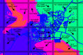
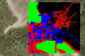
Mask for detailed surfaces in Corazol
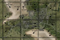
Satellite texture for the same area
Overview of game data


Satellite texture
This texture is mapped onto terrain. In the game, it exists as a group of slightly overlapping squares. Their cutting and overlay is controlled by value of Satellite grid in Tools > Project Parameters.
- Prepare a PNG of the same size you used as input for Satellite Grid value calculation in Project Parameters. In Arma maps, 1 px corresponds to 1 m^2, therefore the map size in meters is equal to raster size in pixels.
- File should be named using suffix _lco, ensuring its proper conversion to PAA.
Hint: If you experiment with satellite texture and you need to regenerate it often, you may as well use _draflco suffix,
which causes binarization to use faster but less accurate conversion of generated segments to PAA. Don't forget to delete
content of Layers folder when you change suffix of source rasters to _lco.
Surface mask
- Size of surface mask should be the same as the size of satellite texture.
- Surface colours in mask should be discrete to avoid any artifacts on map surface in game. Avoid smoothing or anti-aliasing. (Such things are possible but not too easy to make properly, you should follow the gradient depicted in mapLegend.png).
- It is possible to use only 4 colours on each single segment of satellite mask (note: Visitor divides both input rasters in the same way). It is because of the colour conversion of mask segments into 4 full RGB shades (black, full R, full G, full B). In your first projects, it is safer to use just 4 surfaces for the whole map and add more later as you become to know where exactly the source data is cut based on generated satellite segments.
Surface definitions in layers.cfg
- RGB values in layers.cfg must correspond to shades used in mask raster.
- Surface class defines one surface and defines its own set of detailed textures.
- If you used the same surface names as in Arma, same clutters will be displayed in the game as on original Arma surfaces.
class Layers ///List of detailed surfaces in map
{

  class pisek
  {
    texture = "ca\desert\data\pisek_mco.png"; ///Overlay texture on mid-distance, visible with sat. texture
    material="ca\desert\data\pisek.rvmat"; ///File defining detailed textures
  };

  class travajih
  {
    texture = "ca\desert\data\travajih_mco.png";
    material="ca\desert\data\travajih.rvmat";
  };

  class mesto2
  {
    texture = "ca\desert\data\mesto2_mco.png";
    material="ca\desert\data\mesto2.rvmat";
  };

  class pole1
  {
    texture = "ca\desert\data\pole1_mco.png";
    material="ca\desert\data\pole1.rvmat";
  };

};

class Legend ///
{
  picture="ca\desert\Source\mapLegend.png"; ///Path to mapLegend file
  class Colors
  {
    /// Colours must correspond to surface names
    pisek[]={{255,255,0}};
    travajih[]={{0,255,0}};
    mesto2[]={{0,0,255}};
    pole1[]={{99,55,0}};
  }
};
Translation:
- pisek - sand
- trava - grass
- jih - south
- mesto - city
- pole - field
Inserting and editing of objects
Insert to object list - object template definition
- As a first step, you need to insert all the objects you'de into Panel of objects. You can do so using menu Tools > Nature/Artificial Objects. Depending on the list on which model is inserted, it will be hidden/shown when particular filter is activated, there is no other functionality in this classification.
- Objects (*.P3D) can be inserted by clicking Add/Browse button. In Visitoru, objects exist as so-called object templates, defined by theri template name, used model, and ranges for randomizing orientation and size on insertion.
- Deleting object templates from list is possible only if template is not present in the map.
- In Defined Objects window, it is possible to change name, draw properties and randomization of size, pitch and facing of selected object.

Inserting objects in the map
- Choose an object in Panel of objects and insert it bz LMB click on the map.
- Select inserted object by LMB click. It can be edited further:
- Delete (Delete key)
- Move by dragging by mouse
- Change its properties (Object properties), ccessed by double-click or Enter key. It is possible to change:
- Object position
- Rotate selected object
- Elevation relative to surface (meters)
- Object size (%)
- By dragging over objects while holding LMB, multiple objects can be selected. If CTRL/SHIFT is hold, objects are added/substracted from selection.

Hint: If you place mouse cursor over object and press O key,
object will be highlighted and selected in Panel of objects.
Named selections
- If the panel is not visible, it can be activated by View > Named Selections Panel.
- When objects are selected, it is possible to make named selection of them, which can be hidden, locked etc. separately.
- Context menu for named selections can be activated by RMB click in list of selections.
Editing terrain and objects in Buldozer
- As soon as satellite textures import is finished and you want to start with adding objects, it is possible to run Buldozer. You may do so using menu (Project > Connect to Buldozer), CTRL+F7 key or by clicking red exclamation icon in the toolbar.
- When Buldozer is started for the first time ot you changed any textures (regenerating satellite segments, altering objects texures), Buldozer will start converting all PNGs or TGAs to PAA format, which may take a while. If application would seem not to respond, do not try to terminate it and let it finish its job.

Buldozer controls:
- You can navigate in the map using mouse.
- Camera rotation is controlled by numpad (2,4,6,8).
- Zoom of camera relative to cursor is handled by numeric +,- keys.
- Default distance of camera from cursor is restored by numeric key 5.
- LMB selects object (if you select objects in Visitor, they are selected in Buldozer as well).
- Objects are rotated by holding RMB and dragging mouse sideways. Origin of rotation is defined by the position of box cursor.
- LShift key accelerates camera rotation and cursor movement.
- Use H to turn on/off arrow marking closest terrain vertex.
- U/J rises/lowers vertex by 1 meter.
- I/K rises/lowers vertex by 5 meters.
Hint: If you don't see editing cursor (white box) and arrow indicating selected objects, set Buldozer to use content
of unpacked UI.pbo by stating it in text file loaded when Buldozer starts. Description can be found in Visitor 3 Manual page.
Packing your map
- In order to pack the map PBO correctly, you need to have functional config.cpp (+HPP), WRP file, textures in PAA format and all relevant RVMAT files.
- If you use your custom objects in the map, you should pack them and add them to ..\Arma\Addons\ folder before trying the map in game.
- Please note that structures described here reflects working customs of BI. Public utility used to pack PBO files packs ALL the content of a designated addon folder (in this case ..\ca\Desert), therefore it is wise to keep clean "packing" version separated and keep there only needed files.
Hint: If you cannot see your map in map list, game crashes after you attempt to preview mission on your terrain
or you cannot see surface textures, check ALL PATHS in config.cpp and RVMAT files in Data folder. Also make sure
the referenced file really do exist on specified location.