
Weapon Optic Creation – Arma Reforger
Goals
Structure Preparation
While sticking to official structure is not mandatory and there are no engine restrictions asset wise about it, it is recommended to follow guidelines listed here - Data (file) structure - to ensure that all automation plugins are parsing your assets correctly and make it later easy to navigate.
Therefore, your first task will be preparing following file structure

Mesh preparation
General
In principle, mesh preparation is not that different from weapon preparation itself. Again, orientation of the mesh is very important and there are few extra elements needed on the model which are described below.
When it comes to the mesh itself, keep in mind that rear part of the scope will be really close to the players camera when aiming down sights so its worth investing extra polygons in that place. For instance, don't be afraid to use 32 or more sides for cylinders right in front of the player eye. If you are worried about performance impact, you can reduce poly count quite sharply in next LOD, so that detailed mesh will be visible only when player is really close to it.
Colliders
Accessories should have collider with two collision layers - Weapon & FireGeo.
Weapon layer preset is responsible for physical interaction of the accessory, like collisions with other objects, while FireGeo is used for collisions with projectiles and also for detection of inventory actions. In case you don't see your actions in game, double check if item is using correct Layer Preset.
Depending on the complexity of accessory, collision of optic can be done either with single collider convex (UCX or UBX), which is using WeaponFire layer preset or by using two colliders - one simple convex (UCX) collider for Weapon layer preset and second, more complex trimesh (UTM) collider for FireGeo preset. In case of Sample Optic, second method was used.

In both cases, it is recommended to use one of the Weapon_xxx Game Materials on those colliders like:
This will ensure that attachment doesn't stop every bullet on impact.
Memory points
Slots

Attachments like optics are attached to slots and while technically it is not mandatory, adding snap point is a very handy thing. Procedure for adding that is same as on weapon. Below are few tips regarding
- Place snap_weapon empty object at location, where you want to snap with the weapon. See Weapon Slots and Bones page for more details.
- snap_weapon works together with slot_optic point on parent weapon
- Without snap_weapon point, origin of the model would be used for snapping
- In case of RIS rail, middle point in Y axis is sort of way to go.
- Some freedom is allowed though - for instance accessories like Carry Handle Optics, middle location would most likely make it an unusable accessory on most weapons
Points
In order to make configuration of SCR_2DPIPSightsComponent component bit easier, it is recommended to add few points directly in model for setting things like eye position when aiming down sight and front/rear points for camera calculation. Sample Optic has two sights - primary, optical sight with 4x zoom and backup ironsights located on top of it.
Starting with primary sight, perform following actions:
- Create optic_rear empty object at the middle of ocular
- Create optic_front empty object at the front glass
- Create eye empty object - it should be placed few cm away from the middle of the ocular
- This point will be used for main optic, when character is aiming down sights (ADS

- Create eye_ironsight - place it in line with ironsights located at the top of the optic
- This point will be used for backup ironsights

Creating Optic Mesh for PIP

Next step in weapon optic creation is adding additional mesh to the scope on which scope view will be rendered. This can be done in few steps:
- Create flat mesh for picture in picture (PIP) sight rendering and place it at the ocular
- Scope view will be rendered on this surface so make sure it is detailed enough
- UVs of that mesh should cover whole UV island
- If texture is not render correctly (i.e. rotated by 45 degrees to the left or right) and you are sure that , make sure that UVs are rotated correctly
- Create new material called for instance "Optic_pip" and assign it to mesh created in previous step

Additionally, it is a good idea to have additional layer of mesh in front of the PIP selection which has glass like material with some tint and subtle reflections. To do so, follow below steps:
- Create 2nd, more round and convex, mesh for glass optic. Place it in front of PIP mesh. Additionally, you can also use same mesh on the opposite side of the scope
- This is mesh would be only used as eye candy, showing i.e. glass reflection, so don't be afraid to put some extra polygons there
- Create new material called for instance "Optic_lensglass" and assign it to mesh created in previous step

Model Import & Registration

Once that is done, it is possible to import the model into Workbench. Process itself is same as for the weapon, so refer to Model Import & Registration segment of Weapon Creation tutorial.
After model is imported, open it in Resource Manager and change default materials which are assigned to Optic_pip & Optic_lensglass material slots. A nice starting point could be simply assigning to those fields following materials:
- Optic_ARTII_Lensglass.emat to Optic_lensglass slot
- Optic_PSO1_PIPMaterial.emat to Optic_pip slot
Of course, if you wish to make some tweaks to those materials then it is also possible to duplicate above mentioned materials, do tweaks to them and then assign it to the optic you are working on.
Since this model is using empty objects as snap/slot points, it is necessary to check Export hierarchy in Import Settings section. Of course, once this step is performed, don't forget to click on Reimport resource button!

Texture & Material
Reticle

Next step in optic creation will be making of a reticle texture. Create a new texture in graphic editor of your choice and start painting the texture. In case of Sample Optic, TGA texture with Alpha channel was used. In Alpha channel section, which is supposed to be transparent was painted in black.
Vanilla reticles also tends to use PNGs with transparency in the background although creation of such might be troublesome if software that you are using doesn't allow preservation of RGB values when alpha is set to 0.
Below are few tips to keep in mind while making such texture:
- 1024x1024px size is recommended for smaller, less detailed reticles
- If its needed, higher resolution could be used but caution is suggested
- Reticle should fill most of the canvas
- Color of the reticle doesn't mater - it is later replaced by the engine - therefor using just white for the reticle is recommended
- To fix reticle texture blurriness or artifacts you can either:
- Change manually in reticle EDDS Import Settings two parameters - Conversion Quality to 100 and uncheck Generate Mips checkbox. In this scenario, you need to use _UI suffix for your textures!
- Replace the Configuration section of .meta file (open it in text editor) as following, then reimport the texture. You might use _Reticle suffix for your texture
- To fix reticle texture blurriness or artifacts you can either:
Configurations {
 TGAResourceClass PC : "{33F97FFE35E57E1D}Configs/System/ResourceTypes/PC/TextureReticle.conf" {
 }
 TGAResourceClass XBOX_ONE : "{0B42FA7CFD77120F}Configs/System/ResourceTypes/XBOX_ONE/TextureReticle.conf" {
 }
 TGAResourceClass PS4 : "{C1FA7DC8973FA4A1}Configs/System/ResourceTypes/PS4/TextureReticle.conf" {
 }
 TGAResourceClass HEADLESS : "{9664EF94CE7C4525}Configs/System/ResourceTypes/HEADLESS/TextureReticle.conf" {
 }
 TGAResourceClass XBOX_SERIES : "{A4AA0C6FDF186747}Configs/System/ResourceTypes/XBOX_SERIES/TextureReticle.conf" {
 }
}
Material

With reticle textures ready, it is possible to prepare material for picture in picture sight:
- Duplicate one of the existing optic HDR materials (HDREffect class) like - Optic_ARTII_HDR.emat . In this case this file was called Optic_SampleOptic_HDR.emat
- Open that new material and in Details tab locate Reticle Map property.
- Assign previously created reticle texture to Reticle Map property and save the material with Ctrl + S key combination.
Rest of the properties can be left unchanged compared to source material although some tweaks to effects are permitted if you i.e. want to achieve some tint on the PIP view. T
Prefab
Creation
Next step in Optic creation is preparing a prefab.
- Create new prefab which inherits from WeaponOptic_Base.et prefab
- Alternatively you can try to duplicate one of the existing scopes like PSO-1or ART II scope
Once prefab is duplicated, start editing it in for instance Prefab Edit mode and adjust following parameters
- Assign scope mesh in Object property of MeshObject component
- Check Model Geometry option in RigidBody component - this will ensure that interactions with the item are working correctly and that it is possible to pick up this attachment from the ground
This should be enough to see your accessory in the World Editor, although there is more to do to get it to work properly.
Inventory configuration
With some basic prefab configuration in place, it is time to move on to setting of inventory parameters, which affects things like appearance, mass and size in loadout system, character modifiers when scope is equipped and also compatibility of attachment with weapon slots. All of these things are configured in the InventoryItemComponent component, and that's where tweaks need to be made.
Inventory system configuration

Starting with inventory configuration, this part is quite similar to what was already described in Weapon Creation tutorial, so below is quick recap (with differences) of what has to be done in Attributes section of InventoryItemComponent
- Item Display Name
- Adjust Name & Description - both will be shown in in-game inventory system
- Name need to be localised - otherwise item will be displayed incorrectly in for instance Attach action visible in weapon inspection mode
- Adjust Name & Description - both will be shown in in-game inventory system
- Item Phys Attributes
- Adjust Weight - weight in game affects for instance how fast character is tired. Try to use real life values here (of course, if such data is available) - other wise you might try to set value similar to other scopes with similar dimensions.
- Change Size Setup Strategy to Manual and adjust Item Dimensions & Item Volume - those two parameters define much space this item will occupy in containers (like pouches or bags) that are available to player. In case of accessories it is recommended to use Manual mode, since Volume mode might result in an item where you cannot put it anywhere in inventory.
- Change Resting UP parameter to Right
Unlike as on weapon, Item Animation Attributes should be left empty/undefined.
Next on the list is setting of the visual appearance of the scope in loadout view. Parameter related to it are stored in Custom Attributes section of InventoryItemComponent inside of PreviewRenderAttributes class. Over there, you can find familiar looking attributes which were mentioned in Weapon Creation tutorial. In case of Sample Optic, default values were good enough but of course, depending on the accessory that you are making, some adjustments to Camera Orbit Angles or Camera Distance To Item might be required.
Character modifiers setup
In CharacterModifierAttributes class inside Custom Attributes, it is possible to change behavior of the character when given accessory is attached to currently used weapon. WeaponOptic_Base.et contains some of the values typical for scopes, like ADS Speed Limit set to 1.5 m/s - this parameter dictates how fast character can move when aiming down sights. In most cases, 1.5 value is fine for scopes but if you are trying to achieve some more snappy optic, then increasing that limit might make sense. Similarly, reducing that limit to even lower value could be a valid method if you are dealing with some large optic with high magnification.
Attachments configuration
In Custom Attributes section of InventoryItemComponent attributes you can find WeaponAttachmentAttributes class, which has one important parameter - Attachment Type. This parameter, similar to Magazine Well class, controls what type of attachment it is and where it can be attached.
Since Sample Optic is using a RIS rail, one of the RIS attachment classes should be selected. If you are creating some non standard rifle, then take a look Magazine Well configuration paragraph - process is very similar to creation of new attachment.
- AttachmentOpticsRIS1913
- Optics like scope + night vision sights combos can be attached to it
- Length of this rail is above or equal 250mm
- AttachmentOpticsRIS1913Medium
- Optics like larger scopes, collimator + magnifier combos or similar can be attached to it
- Length of this rail is up to 120mm
- AttachmentOpticsRIS1913Short
- Optics like collimators, scopes or similar can be attached to it
- Length of this rail is up to 120mm
- AttachmentOpticsRIS1913VeryShort
- Optics like small collimators, ris ironsights or similar can be attached to it
- Length of this rail is up to 80mm
How does it work in practice? If weapon attachment slot is using AttachmentOpticsRIS1913Medium, then scopes which are using AttachmentOpticsRIS1913Medium, AttachmentOpticsRIS1913Short or AttachmentOpticsRIS1913VeryShort can be attached to it. If weapon has slot with AttachmentOpticsRIS1913VeryShort then only scopes with AttachmentOpticsRIS1913VeryShort Attachment Type can be used on it and AttachmentOpticsRIS1913Short or larger cannot be attached to such slot.
In this case, Sample Optic is longer than 250mm so AttachmentOpticsRIS1913 was picked.
Optics configuration
Configuration of the optic is stored in SCR_2DPIPSightsComponent component. As name suggest, this component enables both 2D & PIP mode on the scope depending on the preferences selected in Gameplay section of the in-game settings.
Diagnostic tools
Before proceeding any further, it is recommended to enable some of the debugs located in Diag Menu located in GameCode > Weapons category. Main debugs for reticles are:
- Show optics diag - used to debug, experiment and verify reticle or scope settings
- The debug rendering circle in PIP can be inaccurate. It has precise on screen angular size in 2D optics mode
- Show PIP settings diag - used to debug Picture in Picture related scope settings
Both of the above debugs will be available only when you are aiming down sights. Once you have enabled one of the debugs mentioned above, you will be able to move the debug window to preferred place by simply holding combination of keys required to show the Diag Menu and then using mouse to drag it. With same key combo, you can also click on the one of the fields to change data in the debug window.

Additionally, it is recommended to enable following debug options in GameCode > Weapons category:
- Disable aim modifiers - disables weapon sway - this is especially handy when trying to do some small tweaks to zeroing
- Disable character aim modifiers
- Disable weapon offset
Setting base sight properties

Starting with properties defined in BaseSights section of SCR_2DPIPSightsComponent, following parameters, affecting general view properties, need to be adjusted:
- Set Sight FOV Info by clicking on set class button next to it and selecting one of the available classes:
- SCR_SightsZoomFOVInfo for fixed power scopes
- Set Base Zoom to match the lowest magnification
- Set Zoom Max to match the highest magnification
- Since Sample Optic has fixed 4x magnification, both Base Zoom & Zoom Max were set to value 4.0
- SCR_VariableSightsFOVInfo for variable power scopes
- SCR_SightsZoomFOVInfo for fixed power scopes
Next on the list is setting of various Sights Points. Above you can find picture showing how they located
- Set Sights Point Rear by clicking on set class button next to it and selecting PointInfo class
- If you have placed empty object in the model itself like it was mentioned before, you can select in Pivot ID property optic_rear
- If you don't have such object or you want to tweak position compared to position provided by Pivot ID, then use Offset & Angels parameters and place this point at the center of rear ocular
- Set Sights Point Front by clicking on set class button next to it and selecting PointInfo class
- Select optic_front in Pivot ID parameter or set offsets manually
- Point should be placed straight in front of rear sight point (X and Y should match) on the plane of the Objective - front glass
- Set Sights Position (main camera eye) behind the rear sight
- Sights Point Rear , Sights Front Position and Sights Position should all be aligned on single axis for simplicity sake
- Use Camera Offset property to move camera to middle of the objective if the objective is in not aligned with Sights
- Use Camera Angles property to rotate the scope camera if necessary
- Enable Sights Priority parameter if you want to automatically use that optic when its attached instead of i.e. ironsights.

Setting 2D scope
2D scope configuration involves making changes in two sections of SCR_2DPIPSightsComponent - Sights & 2DSights. As name might suggest, Sights section contain elements which are shared between both 2D & PIP modes.
Scope view
- Set Objective FOV in degrees
- Try to find real life value, searching for "optic name FOV" should usually yield some results.
- Examples: Field of View value of PSO-1 can be found on Wikipedia , and TA-31RCO specification is published on producer page
- Sample Optic is sort of fictional design loosely based on some existing carry handle integrated sights like G36 or VHS-2 have. Usually, such scopes suffered from poor to mediocore FOV so in this case it was set at 4.9 degree - bit more that Colt 4x20 but less than PSO-1
- Try to find real life value, searching for "optic name FOV" should usually yield some results.
- Set Magnification in Sights section to match Base Zoom in Sight FOV Info
- Tweak Objective Scale so that the optic does not leak out of Full HD 16:9 screen (recommended, optional) - expected values are between 1 and 0.5
- Tweak Vignette scale similarly, style it as you like

Reticle

Next step will be configuration of reticle itself. Steps to that are listed below:
- Set Reticle Texture and Reticle Glow Texture
- Here you should assign texture created in previous steps
- Set Reticle Base Zoom - this will define whether reticle will behave like front or rear focal plane optic
- For front focal plane reticle, this should be set to zero
- Front focal plane reticle stays the same in relation to target no matter the magnification. In other words, reticle changes its size depending on the current magnification.
- For rear focal plane reticle, this should match Magnification or any zoom level that should be used as reference for Reticle Angular Size
- Rear focal plane reticle stays the same in all magnification levels.
- For front focal plane reticle, this should be set to zero
- Set Reticle Angular Size in degrees
- Reference marks angular size/distance
- The further away these marks are from each other, the better
- Set Reticle Portion in percent
- Part of reticle that should match the specified Reticle Angular Size, allowing quick adaptation and verification of different reticle textures
Example 1: PSO-1

PSO-1 small vertical markings are spaced in 1 USSR mils apart. Large notch with number 10 below it represents 10 Warsaw Pact miliradians from the center of the reticle.
As it was mentioned above, the large the distance, the better result, so in this case distance between two large notches with 10 under was used. Those notches are 20 Warsaw Pact mils apart and we still need to convert it to degrees. This can be done using miliradian conversion table - from that page you can get that one Warsaw Pact milliradian equal to 0.06 degrees.
By doing quick math, we get Failed to parse (SVG (MathML can be enabled via browser plugin): Invalid response ("Math extension cannot connect to Restbase.") from server "https://wikimedia.org/api/rest_v1/":): {\displaystyle 20 * 0.06 = 1.2} degree, which can be filled in Reticle Angular Size parameter field.
Next, Reticle Portion parameter can be quickly determined by measuring distance in pixels between previously used reference points (large notches with 10 under it - see picture on the right side) in 2D software (GIMP/Photoshop) and then determining proportion of that distance to total width of reticle image.
In this case PSO-1 the horizontal 10 mils marks are 304 pixels apart on 1024x1024 texture. By dividing that distance by width, we get the ratio which can be filled in that parameter Failed to parse (SVG (MathML can be enabled via browser plugin): Invalid response ("Math extension cannot connect to Restbase.") from server "https://wikimedia.org/api/rest_v1/":): {\displaystyle 304 / 1024 = 0.29687}
Example 2: Sample Optic
Sample Optic is sort of semi fictional design so no concrete data is available in this case. Usually reticles, on such sights with poor FOV, takes large portion of AFOV. Since this scope was set to 4.9 degrees of FOV, setting Reticle Angular Size parameter to 2.2 seems plausible.
Reticle of Sample Optic fills most of the texture, which is kind of the most efficient method quality/file size wise. Reticle itself is 985 pixels wide, while whole textures is 1024x1024px square. By doing quick math and dividing reticle with by texture width (Failed to parse (SVG (MathML can be enabled via browser plugin): Invalid response ("Math extension cannot connect to Restbase.") from server "https://wikimedia.org/api/rest_v1/":): {\displaystyle 985 / 1024 \approx 0.96} ), we get Reticle Portion which is equal to around 0.96.
Setting PIP scope
After 2D settings are set, it is possible to move to configuration of Picture in Picture sight. Parameters related to PIP optic are located in PiPSights section of SCR_2DPIPSightsComponent
Scope view
Starting with scope view, here are steps:
- Tweak sight point distance from rear sight, until apparent FOV matches the FOV of 2D sight closely
- You can switch between 2D & PIP mode in Gameplay section of in game settings. Use F10 key to access pause menu in Workbench


- Tweak Scope Radius until the PIP sight image is as close match with 2D as possible
- Tip: Use Show PIP settings diag to quickly find correct value
- Sight Position attribute Angles can be used to rotate the main camera if necessary
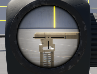
PIP view
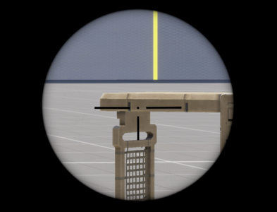
2D view


Reticle
First step in configuring PIP reticle is assigning previously created reticle material (in this case it is Optic_SampleOptic_HDR.emat) to Scope HDR Matrial property in PiPSights section.
Once that is done, perform following steps:
- To avoid misalignment, the reticle movement option in HDR material should be disabled
- Tweak vignette settings in HDR material so that it looks similarly to 2D sight
Arsenal integration
To make your optics more accessible to players in-game, you can add it to the arsenal. This involves including the optics prefab in the Entity Catalog so that it appears in the game's inventory and supply systems.
Include in Entity Catalog:
- Ensure that your suppressor prefab is added to the Weapon Attachments Entities list within the Entity Catalog of selected faction that you want to expose your weapon.Item Type should be set to WEAPON_ATTACHMENT
- Item Mode should be set to ATTACHMENT
- Adjust Supply Cost in line with vanilla
- This allows the game to recognize the suppressor as available equipment.
For detailed instructions on how to add items to the Entity Catalog and configure arsenals, please refer to the Crate Filling section of the Weapon Creation documentation.