Reyhard/Sandbox – User
No edit summary |
|||
| Line 333: | Line 333: | ||
=== Aligning and grouping nodes === | === Aligning and grouping nodes === | ||
= Adding scripted action = | = Adding scripted action = | ||
Revision as of 09:43, 8 August 2022
Goals of this tutorial
In this tutorial you will learn about:
- How to prepare prop in FBX format for Enfusion
- How to import FBX into Workbench
- How to configure new prop in Workbench
- How to add procedural animation with sound & custom action to prop prefab
Setting skeleton & rigging mesh
This asset has six drawers which can be animated. In order to make those drawers animated, it is necessary to add proper skeleton to the model and then skin those movable selections to newly created bones.
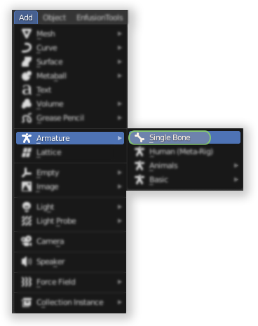
In Blender, new armature can be easily created by adding new Single Bone in Add → Armature menu when in Object Mode. This new bone can be called root and it will be serving as main bone of this skeleton.
Similar to sockets, orientation of bones is quite important for animation. Unlike in RV engine, animations are no longer using two vertices to create axis of transformation but instead rotation & position of bone is used to determine origin of animation.
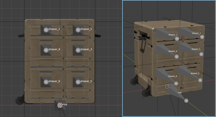
Once root bone was created, it is possible to add bone for each of the drawers like on picture below.
Colliders & material names
Colliders are special type of objects which are used to calculate various kinds of collisions - be it physic simulation or tracing of bullet penetration. There are few rules regarding those colliders and most of them listed on collider related segment of FBX Import page.
When importing asset from previous Arma game - like in this example - you are most likely going to have already convex components ready from Geometry, Fire Geometry, View Geometry or Geometry Physx LODs. If you are using P3D importer which is part of Enfusion Blender Tools, then those components will be automatically converted to trimesh colliders ( UTM_ prefix). Since trimesh colliders are not recommended for general collision, it might be wise to verify if object can be converted to trimesh.
If you are using Blender, there is small handy tool to assist you with assigning correct game materials & layer presets on colliders - more details about can be found on Arma_Reforger:Enfusion_Blender_Tools:_Objects_Tools.
In this sample, rugged desk uses simple box mesh, so usage of UBX_ prefix is recommended.
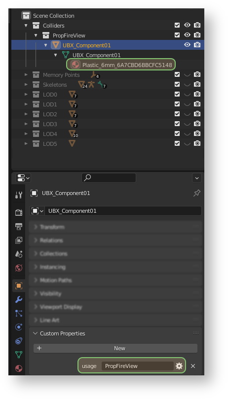
Next thing when it comes to configuration of colliders is configuration of Layer Preset. This is done through usage custom property (details about adding that property can be found on following FBX Import page). For simple prop like this one, layer preset should be set to PropFireView. If you have multiple colliders, you have to add that property to each of them!
After layer preset is set, it is time for setting Game Material. This is done by assigning to collider a material with specific name and again, details of naming are described on FBX Import page. For this example prop, Plastic_6mm game materials is used, since it is assumed that single wall is 3mm thick and due to to geometry is a simple box, those walls are counted twice.
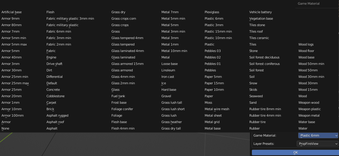
Below is screen showing Game Materials & Layer Presets selection menu from Enfusion Blender Tools. Using this simple tool it is possible to easily select desired game material and layer preset, which will be automatically. Please note that before using that feature it is necessary to sort objects and setup plugin correctly.
FBX export settings
Most of the general rules can be found on FBX Import page . In principle, when exporting from i.e. 3DS Max, you have to make sure that you are exporting in binary format in version 2014/2015. Furthermore, Triangulation & Preserve Edge Orientation should be turned off.
Blender wise, there are 3 most important things to keep in mind when exporting FBX
Preparing textures
When importing textures of weapon from previous Real Virtuality games like Arma 3 there is no real automated or simple method of conversion spec-gloss textures to PBR (Physicial Based Rendering) Metal Rough ones - current industry standard. Therefore in most cases it's much easier to do textures from scratch in i.e. Substance Painter.
There are tons of materials on the internet how to create proper PBR texture and it's highly recommend to search for it via some popular search engines. More information about maps and textures used by Reforger can be found on Arma_Reforger:Textures page
For this asset, assuming that Substance Painter is used, it is recommended to use one of the shared export profiles - Arma Reforger - BCR + NMO, which should create textures compatible with Reforger.
Importing & registering new model
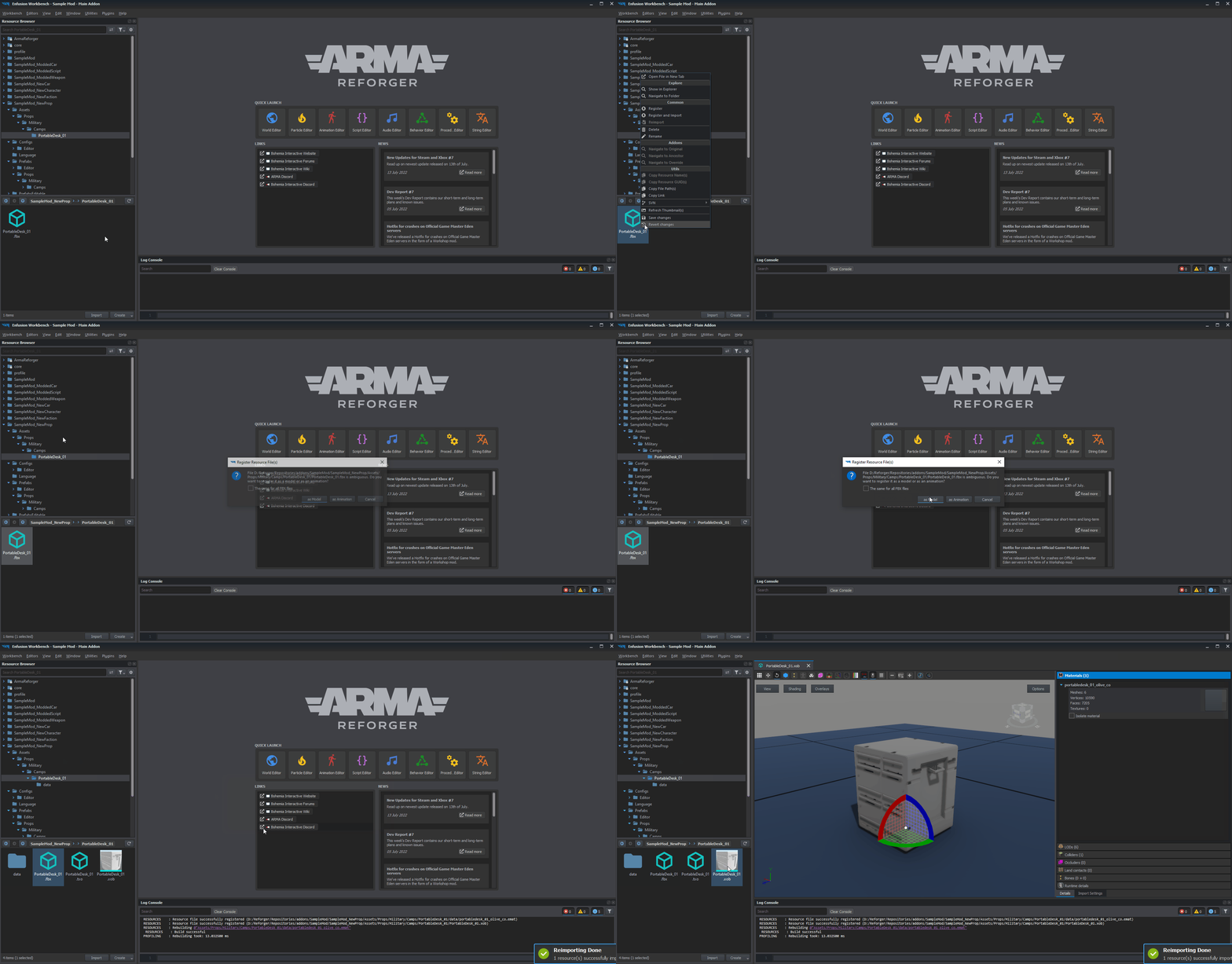
Importing and registering of new model is quite simple and this involves following steps:
- Locating FBX file that you wish to convert in Resource Browser
- Clicking on that FBX with RMB and then selecting "Register and Import" option from the context menu
- From pop up menu with title Register Resource (File(s), select "as Model" option
After that, conversion of FBX into XOB will begin and depending on complexity of the model it might take some time. In case of that simple prop.
Once model is imported, a new XOB should appear in Resource Browser - this file can be now opened in new Resource Manager tab for preview and game related parameters tweaking by double clicking with ![]() on it.
on it.
While Workbench still supports relative paths for materials, this method is discouraged and should not be used.
Import settings
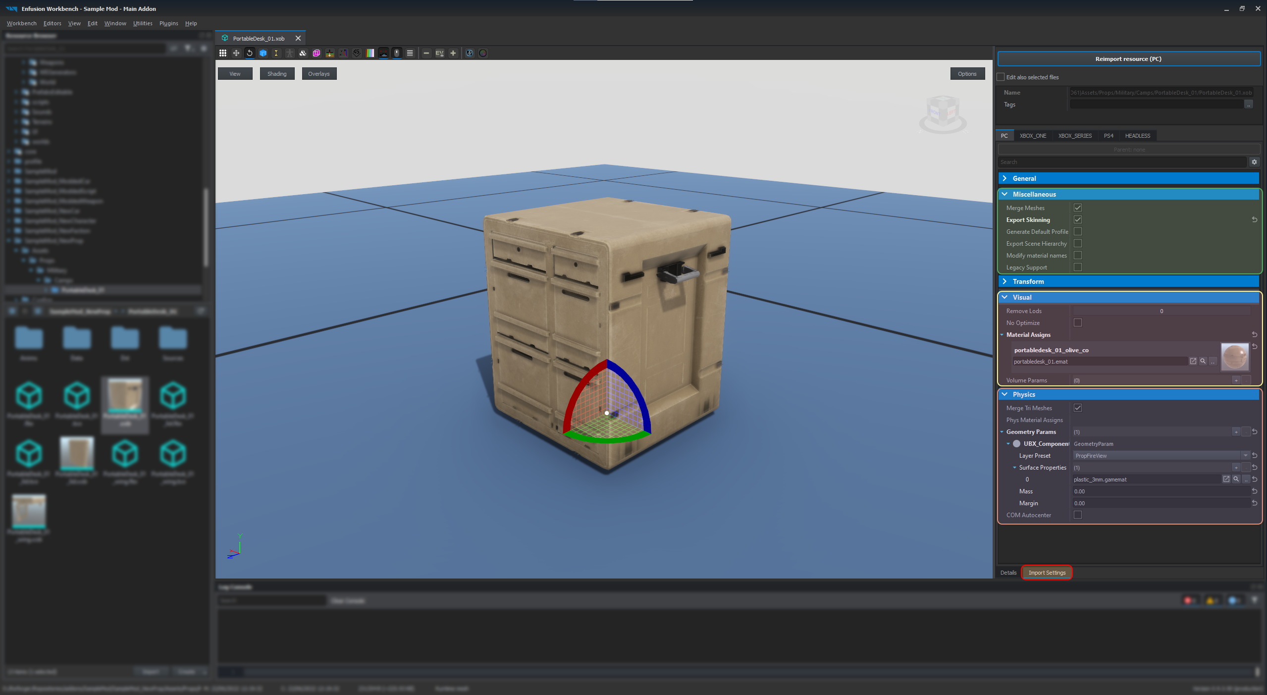
If everything went fine, main Resource Manager window should look like that:
On the right side of the viewport, there is a panel where you can select between two tabs:
- Details - shows various statistics (i.e. vertex, face or face count) and informations about materials, colliders, skeleton or LODs present in the imported model. This tab is by default selected when opening new model.
- Import Settings - in this tab it is possible to modify how FBX is imported to the game and it is possible to modify transformation, materials, physics or other misc parameters here.
After briefly checking if model has correct number of LOD (levels of details) and it looks visually fine, it's time to move to Import Settings tab, where there are couple important things to set.
Physics setup
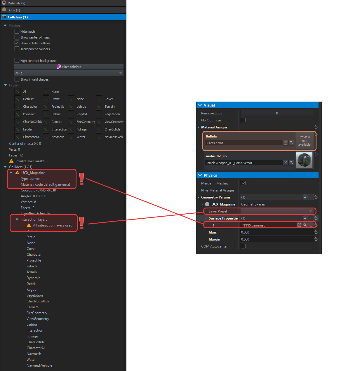
After initial import was done it's time to make sure that materials & colliders are using proper materials & colliders. If it fails to find such texture, new dummy material (see area marked in orange on screen below) will be created in data folder next to the FBX model.
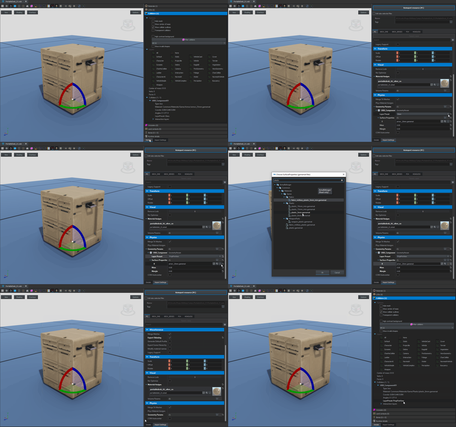
If everything was setup correctly in Blender, imported model should already have one collider imported with correctly assigned Layer Preset (PropFireView) and Surface Properties (plastic_3mm.gamemat). Otherwise, here is the list of some common issues:
Geometry Params list is empty
If both Colliders array in Details and Geometry Params array in Import Settings are empty, check for following errors:
- Check if objects which are supposed to be colliders have correct prefix - i.e. UBX, UCX, etc. See FBX Import page for more information
- Check Console Log if there are no errors regarding convexity or shape of the collider. See FBX Import page for more information
Wrong Game Material
If impact effect on the asset are using default dirt impact effects or following error appears in console
RESOURCES : GetResourceObject @"{411A617924FC3D61}Assets/Props/Military/Camps/PortableDesk_01/PortableDesk_01.xob"
RESOURCES (E): Wrong&patched resource GUID in @"Assets/Props/Military/Camps/PortableDesk_01/PortableDesk_01.xob" for property UBX_Component01 resource name @"Plastic_6m.gamemat"
RESOURCES : GetResourceObject @"{D4D49F200A5937E1}Plastic_6m.gamemat"
RESOURCES (E): Failed to open
then check for following errors:
- Make sure in 3D software of your choice that material assigned to collider is correctly named, i.e. Plastic_6mm_6A7CBD6BBCFC5148 - see Game Material section of FBX Import page.
Wrong Layer Preset
If you see warning triangle Colliders section of Details tab or All interaction layers used error, then check for following things:
- Make sure that collider has correct Layer Preset assigned
- Make sure that Custom Properties option is checked in FBX export settings
Changing parameters
If for some reason you don't want to touch FBX and want to change Layer Preset or assigned game materials in Workbench itself, then it is possible to do that by manipulating Layer Preset & Surface Properties parameters in Physics section of Import Settings tab. Changes to those parameters require usage of Reimport resource button - otherwise information stored in XOB would not be updated. This method is not recommended though.
Skeleton & Hierarchy
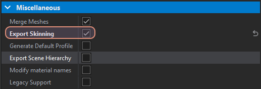
In case of models with skeleton (Armature) it is quite important to check Export Skinning option in Miscellaneous section of Import Settings.
Since Rugged Desk is supposed to have six animated drawers, it is important to enable that option and then reimport the model via Reimport resource (PC) button.
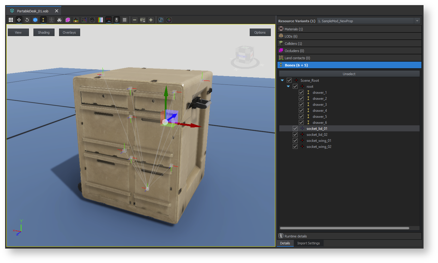
If skeleton was imported correctly', Details tab' in right section of the Resource Manger view port should show some non zero number in Bones section. In case of Rugged Desk, this object should have 6 skinned bones, 4 sockets and one dummy hierarchy element (root), which should be visible as Bones (6 + 5). First number in the bracket indicates number of skinned bones and 2nd one indicates of empty bones (either bones which are not skinned to anything or empty objects)
For Rugged Desk wing & lid it is possible to just use Export Scene Hierarchy - this should allow to use empty objects created before for snapping purposes.
Importing textures
By default, Workbench importer will create new materials (emats) using MatPBRBasic shader in Data folder next to the imported model, based on material names located in FBX. If material suitable for the mesh already exist somewhere in available projects, it is possible to change linked material by changing elements in Material Assigns located in Visual section of Import Settings - this option will be later used for Portable Desk lid & wing, which share same materials.
Once those materials are ready, you can use same procedures as the ones described on Sample Modded Weapon - Documentation - Creating New Materials page.
Adding basic configuration
Creating prefab
Prefabs for props can be prepared in multiple ways and it also depends on amount of functions that are planned to be added to such asset.
In general, it is recommend to use one of those two prefabs as a base:
- Props_Base.et - prefab for simple, non destructible assets
- Destructible_Props_Base.et - prefab dedicated for assets which can be destroyed
Since this sample is planned to have destruction, Destructible_Props_Base.et prefab can be used as a base.
In general, it is possible to create new inherited prefab in two ways:
- By dropping parent prefab in World Editor and drag and dropping that entity into Resource Browser field
- By using Inherit Prefab in Addon on prefab selected in Resource Browser attached to World Editor
No matter what method was picked, it is recommended to create base prefab for props, which might have some variants. In this tutorial Portable Desk have 3 texture variants prepared, so such base class will be more than welcome.
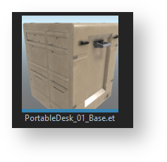
In this case, new prefab, which inherits from Destructible_Props_Base.et , should be called PortableDesk_01_Base.et
Final step in initial configuration will be assigning previously imported mesh. This can be done by simply assigning Rugged Desk XOB into Object property of MeshObject component in PortableDesk_01_Base.et prefab.
If change was applied to MeshObject component of prefab instance, don't forget to press Apply to prefab button and then save currently loaded world!
Creating texture variants
Since this assets is supposed to have three color variants, new prefab variants have to be prepared
- Create new prefabs, inheriting from PortableDesk_01_Base.et, either via World Editor viewport drag and drop method or via Inherit Prefab action available in Resource Browser attached to World Editor
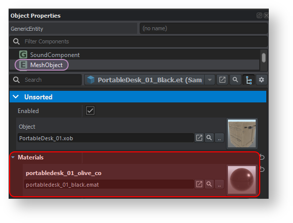
- Once new prefabs are created, open them and one by one, change assigned materials in Materials array inside MeshObject component to appropriate material created before.
- Apply changes to the prefabs if changes were applied to entity instance, otherwise (if hierarchy tree was used) this step can be skipped
- Permanently save changes to the prefabs by either saving current world or, if in prefab edit mode, save the prefab directly.
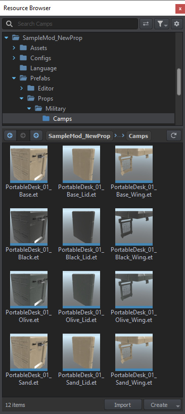
In the end, following files should be present in next to the PortableDesk_01_Base.et
- PortableDesk_01_Black.et
- PortableDesk_01_Olive.et
- PortableDesk_01_Sand.et
Creating prefabs for smaller parts
Procedure described above should be also applied to lid and wing prefabs so they have base prefab (inheriting from Destructible_Props_Base.et ) and color variants. Those prefabs should be really simple at this stage so MeshObject and RigidBody components which they inheriting from Destructible_Props_Base should be enough.
In the end, following set of prefabs should be created
- PortableDesk_01_wing_base.et
- PortableDesk_01_wing_Black.et
- PortableDesk_01_wing_Olive.et
- PortableDesk_01_wing_Sand.et
- PortableDesk_01_lid_base.et
- PortableDesk_01_lid_Black.et
- PortableDesk_01_lid_Olive.et
- PortableDesk_01_lid_Sand.et
Creating prop variants
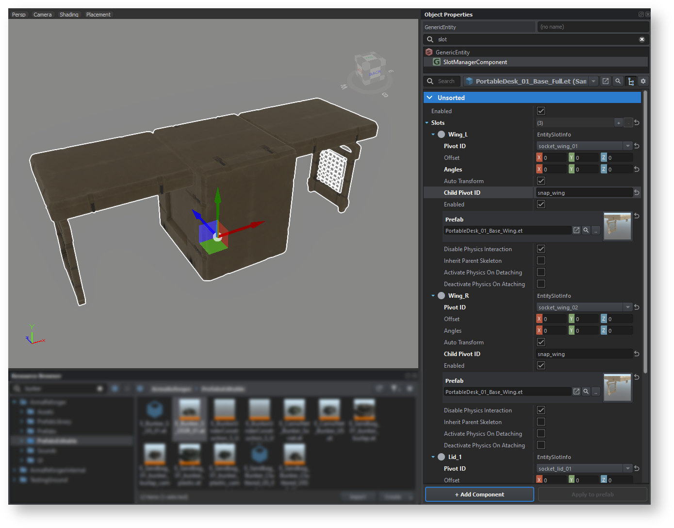
In order to create a variant of Portable Rugged Desk with for instance both wings and lids attached, it is possible to utilize SlotManagerComponent to attach additional elements. Before going any further though, it is recommend to start with creating a new base prefab - PortableDesk_01_Base_Full.et - which will serve as a base asset with all additions attached. Since the core of the desk remains the same, this new base prefab should inherit from PortableDesk_01_Base.et
Once base prefab is there, follow below steps to :
- Add new SlotManagerComponent via + Add Component button
- Select SlotManagerComponent and add new element to Slots array by clicking on plus sign on the right side of that property
- Select EntitySlotInfo from the list that appeared
- Type new name of that slot. For instance slot for wing can be called Wing_L
- In Wing_L element, locate Pivot ID property and select socket_wing_01 from the list
- In Child Pivot ID type name of the snap point which is located in the mesh - in this case it is called snap_wing
- In Prefab property, assign prefab which you want to use - in this case it will be PortableDesk_01_Base_Wing.et
This procedure should be repeated for the rest of the slots - Wing_R, Lid_1 & Lid2. In case the prefabs from the slots are incorrectly attached, please make sure that orientation of sockets and snap points is correct. Otherwise, the new PortableDesk_01_Base_Full.et should look like that:
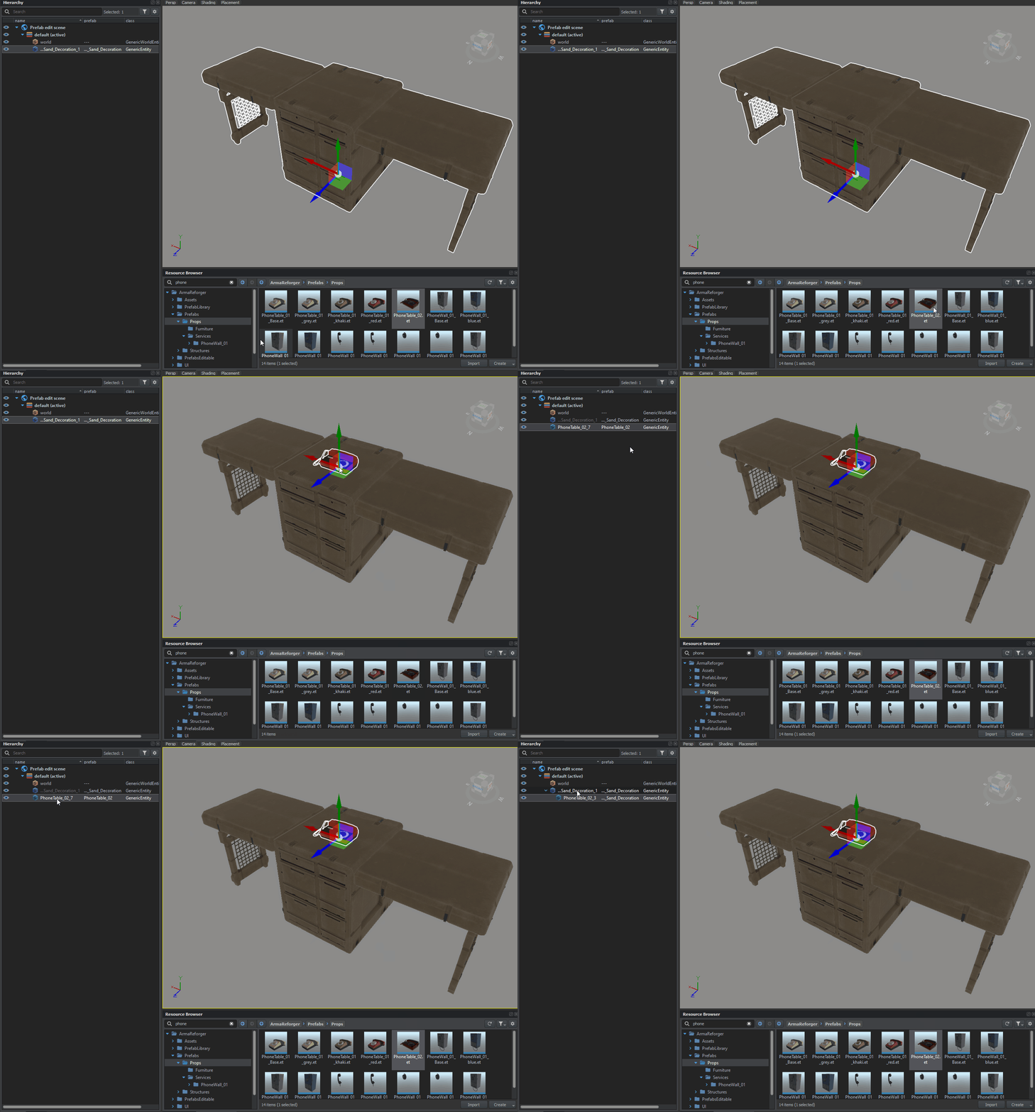
Beside using SlotManagerComponent, it is also possible to utilize hierarchy. This is especially useful when you for instance want to create a mini composition out of prefab, like add a telephone, some notebooks or ashtrays to it. After adding Hierarchy component to both parent and children prefab, it is even possible to utilize Pivot ID to snap prefabs to desired place. There is no way to define Child Pivot ID using that method though and thats why SlotManagerComponent was used here.
Principles of adding entity to prefab are described on Prefabs Basics page
Adding procedural animation
Creating new procedural animation project
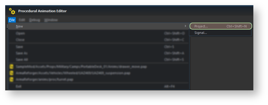
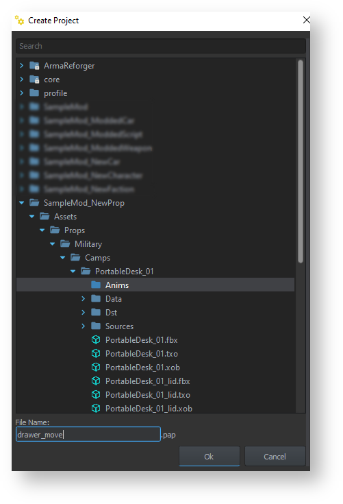
First step in creation of new procedural animation project would be launching of Procedural Animation Editor. After that, new project can be created by navigating to File → New → Project... ( alternatively, Ctrl + ⇧ Shift + N shortcut can be used) in order to create new Procedural Animation Project. Procedural Animation Project is quite similar in purpose to animation definitions in Real Virtuality Model Config but with much better signal processing (more about it next chapter).
Once that step is completed, a new pop up window will appear asking for save location. In Arma Reforger, asset specific procedural animations are stored next to the model somewhere in inside Asset folder structure. Common animations, like turrets or wheel animations which are used by multiple vehicles, are located in Anims/Proc folder.
Here, situation is quite simplified and Rugged Desk animations are assumed to be specific to this asset and are placed in Assets/Props/Military/Camps/PortableDesk_01/Anims/ folder.
Creating new procedural animation signal
Once new Procedural Animation Project is created, it is possible to populate it with actual data. First step towards this goal would be creating new signal. To differentiate it from Audio Editor signals, Procedural Animation Editor signals have .siga extension.
Signals are quite essential part of procedural animation since they are controlling how signals from scripted or engine events are processed. For those familiar with Real Virtuality Engine, signals are somewhat similar in their purpose to source parameter in Model Config - this time though it is possible to do much more complex processing of signals like mixing values, non linear movement and mixing two or more signals together.
Setting up signal
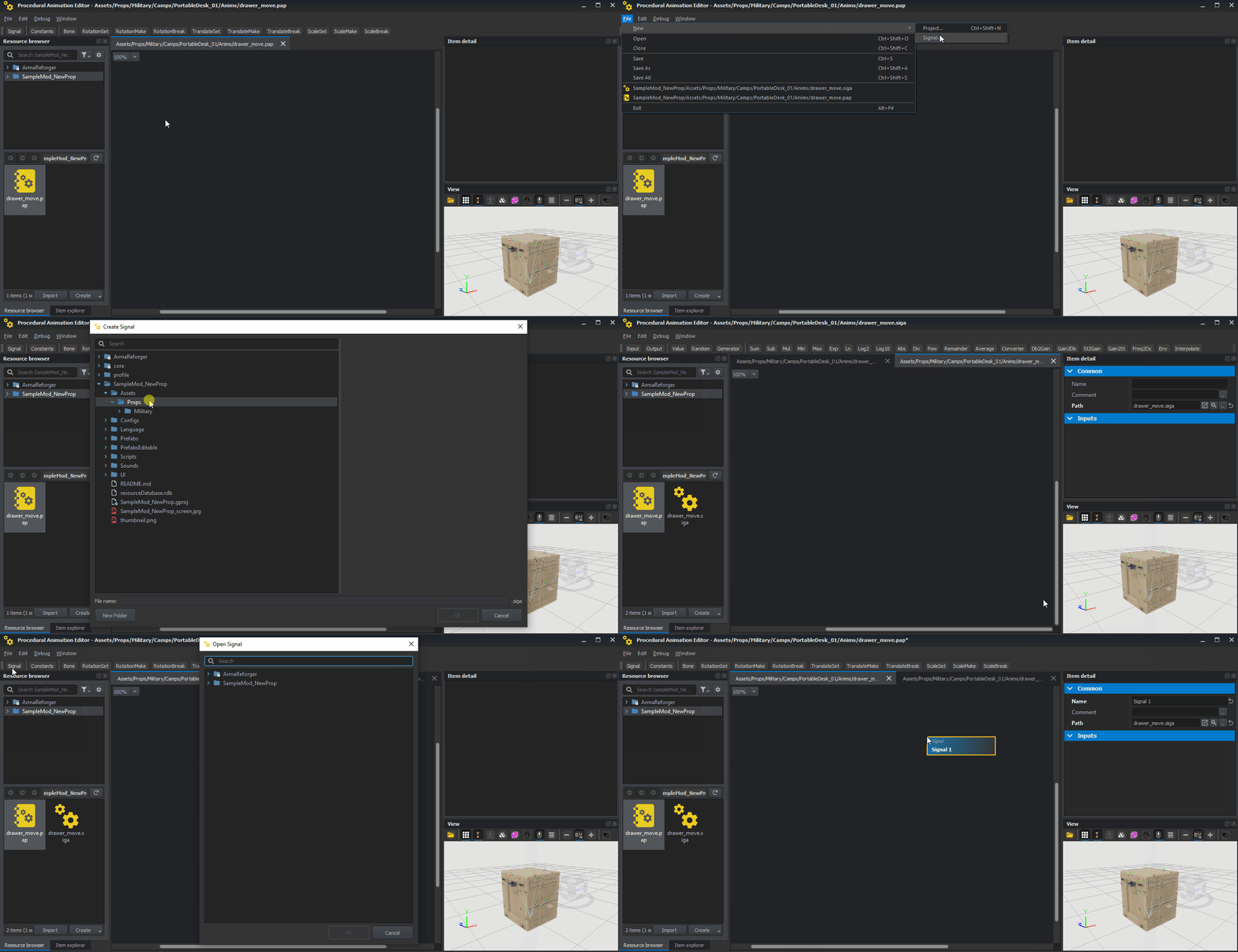
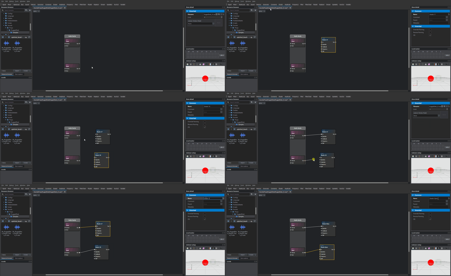
To create new signal, click with ![]() on Signal button located in the top bar of Procedural Animation Editor. After clicking on that, a new pop up window should appear, asking for a location and name of new signal. By default, that Create Signal window should suggest same name (different extension is used - siga) and folder as Procedural Animation Project is using and in case of simple animations like this one, this is a correct solution.
on Signal button located in the top bar of Procedural Animation Editor. After clicking on that, a new pop up window should appear, asking for a location and name of new signal. By default, that Create Signal window should suggest same name (different extension is used - siga) and folder as Procedural Animation Project is using and in case of simple animations like this one, this is a correct solution.
After confirming filename and location, new signal should be created on drive. This new signal file should be also automatically added to current Procedural Animation project - if not, then it might be necessary to drag that new signal to the main window.
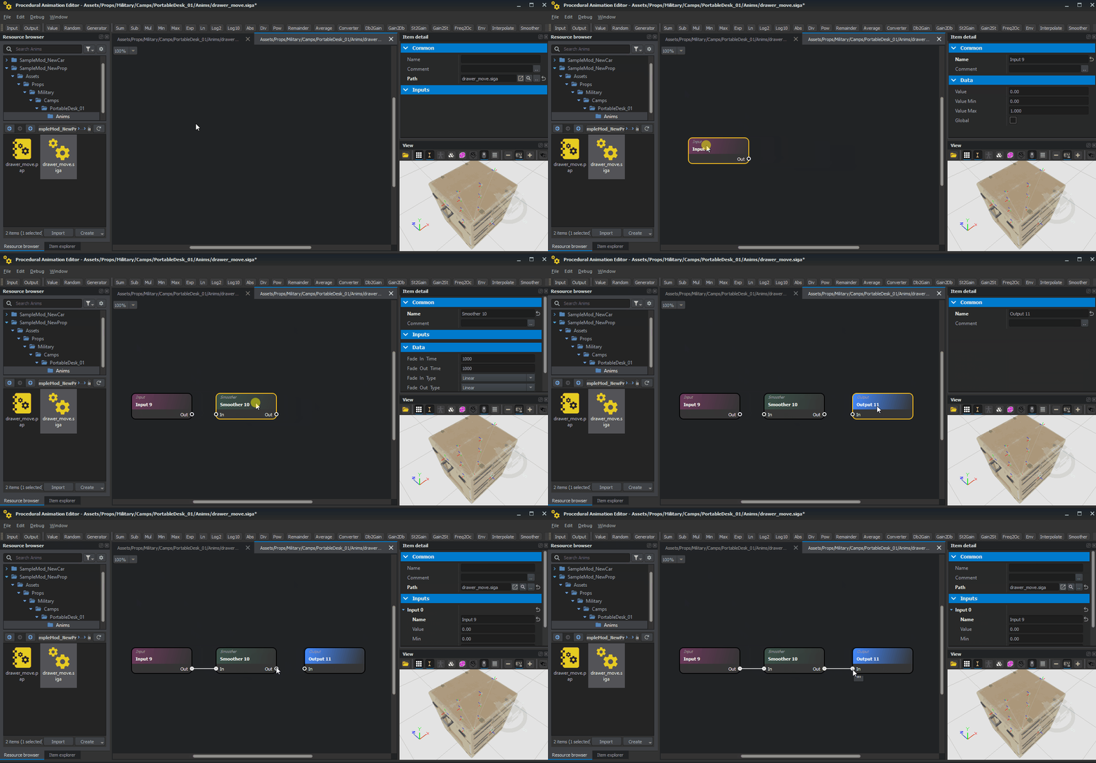
At minimum, signal should contain Input and Output node and those can be added by clicking with ![]() on Input and Output buttons respectively in the top section of main window. At this point, it is possible to simply connect Out connector from Input node to In connector from Output node and such signal would already work. However, beauty of Procedural Animator Editor lies in nodes that can be used to process the signal and therefore, Smoother node will be added in this signal project to, as name suggest, smooth the signal.
on Input and Output buttons respectively in the top section of main window. At this point, it is possible to simply connect Out connector from Input node to In connector from Output node and such signal would already work. However, beauty of Procedural Animator Editor lies in nodes that can be used to process the signal and therefore, Smoother node will be added in this signal project to, as name suggest, smooth the signal.
Same as with the Input and Output nodes, Smoother can be simply added by clicking on Smoother button in top section of main window.
Once that newly created node is present in the window, it is possible to connect Out' from Input node with In from Smoother node'. Similar thing should be done with Output node where its In connector should be linked with Out connector of Smoother node.
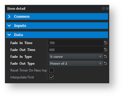
With those nodes being properly connected, now it's time to adjust behavior of Smoother node itself. To do so, click on it and navigate to Item detail window and go to Data section over there.
Fade In Time & Type will correspond to opening of drawer and Fade Out Time & Type to closing of drawer. In this case, Fade In Time was set to 700 and Type was set to S-curve (See {{Wikipedia|Sigmoid function) - this should give it quite nice & natural motion. Closing of the drawer should behave more like you slam it so that's why Power of 2 was selected in Fade Out Type drop-down list.
At later stage, once scripted user action are configured, it might be wise to play with those parameters in-game and observe what kind of results you can get by changing time or type of fade effect.
Once first set of Input, Smoother & Output nodes is completed, it is now possible to create rest of the signals for all separate drawers. This could be achieved in two ways:
- By repeating whole procedure and manually adding Input, Smoother & Output nodes and then, adjusting content of Smoother node
- By using copy and paste procedure
Naturally, since all those signals are supposed to work almost exactly the same, using copy paste procedure is recommend way of dealing with rest of the signal.
To copy paste nodes, simply click and then hold ![]() and select all nodes that you want copy. If everything was done correctly, nodes should have now golden stroke around them. After that, use Ctrl + C combination to copy files and then use Ctrl + V combo to paste those nodes under the cursor. Voila, now this action has to be repeated till signal project has 6 sets of Input, Smoother & Output nodes.
and select all nodes that you want copy. If everything was done correctly, nodes should have now golden stroke around them. After that, use Ctrl + C combination to copy files and then use Ctrl + V combo to paste those nodes under the cursor. Voila, now this action has to be repeated till signal project has 6 sets of Input, Smoother & Output nodes.
Aligning and grouping nodes
Adding scripted action
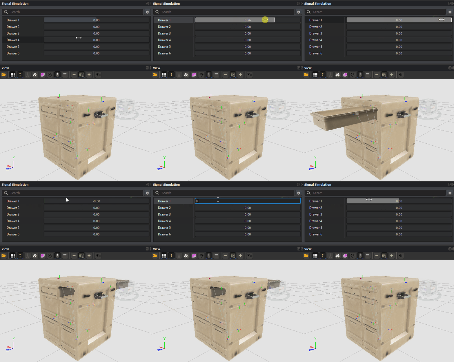
With that knowledge, previewing animations in View window should not longer be a problem
Applying procedural animation to prefab
At this stage, it is finally possible to plug in animation to rugged desk prefab. It will be still not possible to animate it in game via some user action but it will be good base for further endeavors.
First step towards it would be adding two new components to Rugged Desk base prefab
- ProcAnimComponent - links Procedural Animation Projects to prefab and defines which bones are linked to PAP file
- SignalsManagerComponent - enables usage of signals which are either provided by game code or scripts
Those components can be added via Add Component + button located in bottom section of Object Properties window - whole process of adding new components is described in detail on Prefabs Basics page.
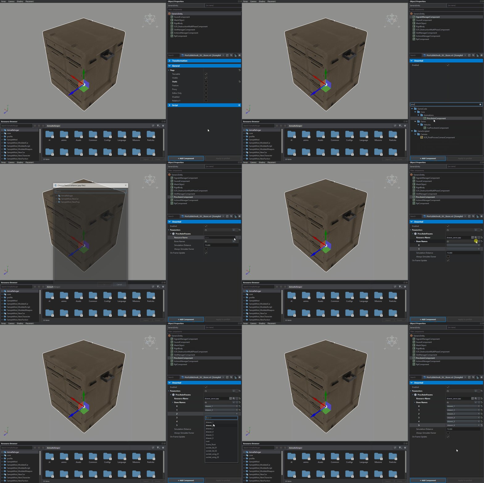
While SignalsManagerComponent basically doesn't need any further tweaking, ProcAnimComponent needs some configuration. In this component, locate Parameters array and add new element by clicking on plus symbol on the right side of that parameter. This should add new element to the array of ProcAnimParams type. Over there, there are two new parameters available:
- Resource Name - this parameter is used to link Procedural Animation Project (.pap) to the prefab. In this case drawer_move.pap should be selected.
- Bone Names - array of bones (list is filled automatically if MeshObject has bones/pivots available) which should be animated. This list should match bones order (the stored in .pap file itself!) and sometimes it might be necessary to verify in game which entry in array corresponds to Bone node in Procedural Animation Project.
If components were added to entity instance of Rugged Desk base prefab, then don't forget to use Apply to prefab button and then remember to save current world to store previously made changes permanently on the drive. After that, initial implementation of procedural animations should be completed.
To add new scripted action for opening and closing of drawers following elements are needed:
- New script for drawer action
- Properly configured Action Contexts and Additional Actions in ActionsManagerComponent
Before going any further, first step towards adding new user action would be adding of ActionsManagerComponent to PortableDesk_01_Base.et prefab. Similar as in applying procedural animation to prefab segment, this can be done in few ways and all those methods are described on Prefabs Basics page.
In this tutorial, it is assumed that user have already some experience with scripts in general. If not, a good starting point might be and then checking one of the scripting tutorials Scripting Example or Scripting Modding.
In Script Editor, in Projects tab, it is possible to check some of the already existing User Actions in Game('Scripts/Game') → Scripts → Game → UserActions. A good candidate for inspiration might be SCR_DoorUserAction which has some of parts, which could be potentially reused for drawer open/close action.
Creating new user action
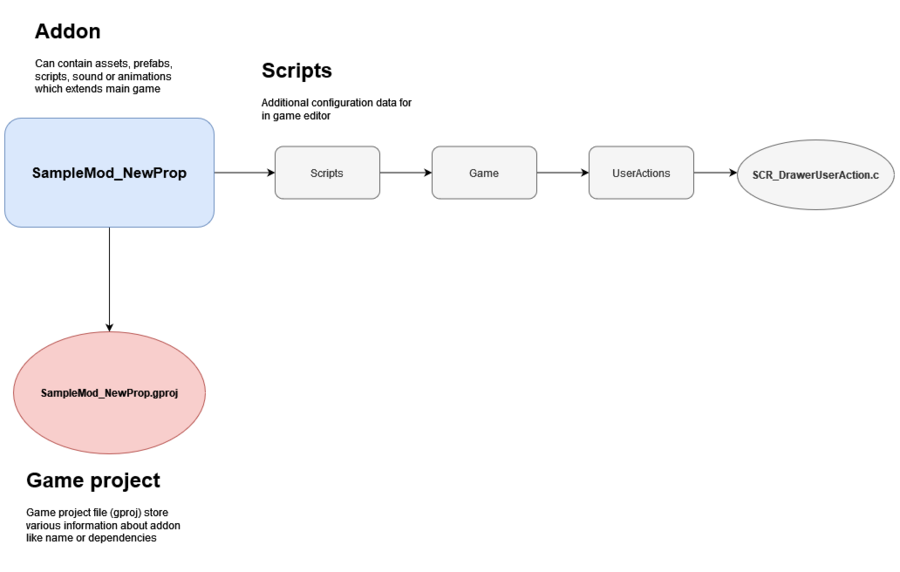
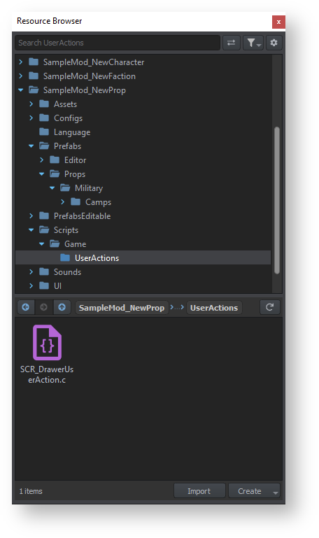
Starting with creation of new scripted user action, it will be necessary to prepare correct folder structure first. In this case, new script should be created in Scripts → Game → UserActions folder.
By default, game is evaluating scripts located in few predefined locations (which are defined in Resource Manager options in Modules section), so Scripts → Game part of the structure is extremely important - script outside of that folder would not be compiled otherwise. UserActions folder is recommendation though since all other vanilla user actions are located over there.
When folder structure is ready, it is time to create a new script called SCR_DrawerUserAction.c. In general, it can be done in at least three ways:
- Via Create button in Resource Browser (doesn't matter if its attached to which editor it is attached, Resource Manager will work fine though)
- To use this method, navigate to Scripts → Game → UserActions folder and then either click on Create button or use RMB on file list. In both cases, a new menu will appear from which you can select Script option. This will
- Via Add New Script... context menu in Projects window
- Via Script Wizard
In principle, to make your new user action selectable in Additional Actions inside ActionsManagerComponent, you have to inherit from ScriptedUserAction class - just like SCR_DoorUserACtion does. This can be simply achieved by writing following code in SCR_DrawerUserAction.c
Next step would be getting reference to SingalsManagerComponent. It is done once in init and reference to it is cached in memory.
Once that is set, it is a proper moment to add new attribute to the action itself. To do so, add [Attribute()] tag above variable that you want to expose. Attributes can be provided in two ways:
- Without parameters names, just values are typed, separated by coma. Example: [Attribute("hello", UIWidgets.EditBox)]
- With parameter names, list of parameters can be checked in Script Editor over there.
In this tutorial, the 2nd method was used.
Above code should translate to parameter being visible in SCR_DrawerUserAction as on picture below. This part is detailed more in detail later, so for now we can continue with writing script.
Further step is finding of signal index in SingalsManagerComponent using name provided by attribute exposed before. To do so, it is necessary to override two methods:
- CanBeShownScript - controls if this action can be performed by the provided user entity
- CanBePerformedScript - controls if this action can be shown in the UI by the provided user entity
In case of CanBeShownScript, work is quite simple since it is assumed that action should be always visible if it can be performed.
CanBePerformedScript does some simple validation of input and verifies if SingalsManagerComponent is present on entity, if not, then the script will exit. Afterwards, code is validating m_iSignalIndex variable. By default it is set to -1 and in such case, code will try to find m_sSignalName in SingalsManagerComponent and return correct index. If its not found, then action won't be visible.
After that, code for sending signal to Procedural Animation Project can be added. This is done by finding signal (via FindSignal method) in SignalManagerComponent, which was automatically registered by linked procedural animation in ProcAnimComponent.
Since setting ValRT in Procedural Animation Projects do a full movement of the drawer, targetValue variable switches between 0 and MAX_SIGNAL_VALUE constants, so the drawer is not fully opened. Of course, this can be changed/optimized and this is mainly a showcase how to work with signals. Value of targetValue is then passed to SignalsManagerComponent through SetSignalValue method, which is finally passed to procedural animation.
Last step will be handling of UI part and changing name of the action depending whether drawer is going to be closed or opened. This is done by overriding GetActionNameScript method and changing outName string. If signal connected to that particular drawer is equal to 0, then we can assume that drawer is closed and action that should be visible by player should be called "Open". Otherwise, "Close" action should be presented to player.
If all described above steps were done correctly, then new, SCR_DrawerUserAction action should be ready to use in ActionsManagerComponent. Below you can find full script code.
Full code
Adding action contexts
With SCR_DrawerUserAction being properly setup, it is possible to move forward and start adding new Action Contexts in ActionsManagerComponent.
Action Contexts serves as a sort of list of interactable places , where other systems requiring user input can use them.
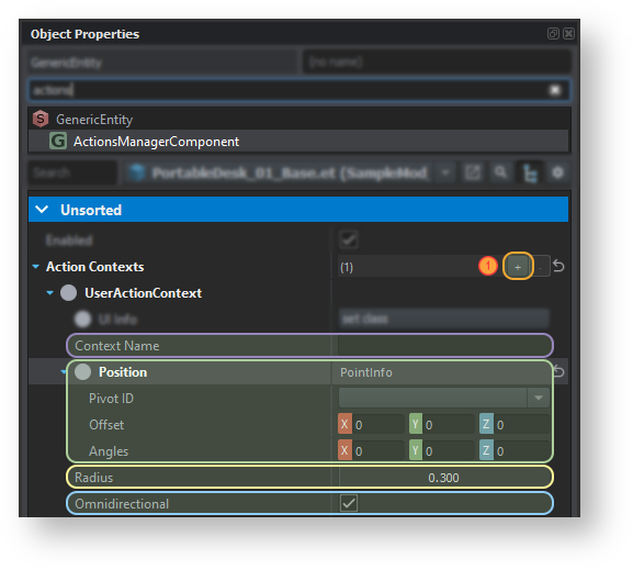
Each action context have following properties:
- Context Name - used by other systems to distinguish this action from the rest of action contexts
- Position - defines position of the action. Using PointInfo class, it is possible to define following things
- Pivot ID - in this drop-down list box it is possible to attach action context to selected bone. Action will follow the bone if its animated
- Offset - offset from the center of model or (Pivot ID has some valid bone selected) from center of the Pivot ID
- Angles - orientation of the action - it is especially important when Omnidirectional property is set to false
- Radius - this parameter defines how far, from the origin defined by Position parameter, action context is visible.
- Omnidirectional - defines if context is available from both sides or not.
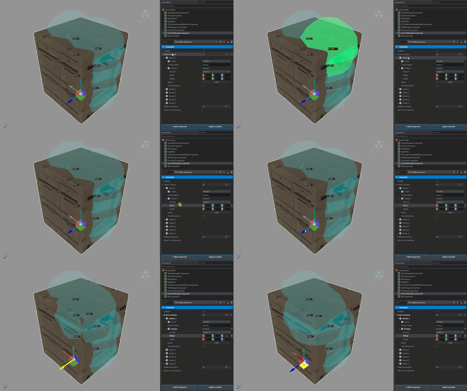
New Action Contexts can be added to ActionsManagerComponent by clicking on plus + sign (1) located to the right of the parameter. ActionsManagerComponent component has also some interesting options available which can speed up process of debug and setup of new actions.
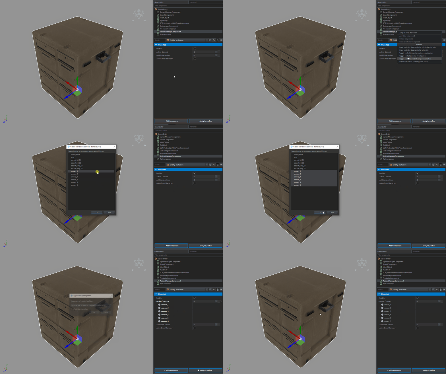
After clicking with RMB on ActionsManagerComponent in Object Properties windows, a new context menu should appear containing various options for debuging and one action for assisted creation of new action contexts - Create user action context(s) from bones.
After clicking Create user action context(s) from bones option, a new window will appear listing all bones that don't have action context defined yet. By clicking on drawer_1 with ![]() and clicking on drawer_6 with
and clicking on drawer_6 with ![]() while holding left ⇧ Shift, you can select multiple entries at once. It is also possible to select multiple elements by holding left control and then clicking with
while holding left ⇧ Shift, you can select multiple entries at once. It is also possible to select multiple elements by holding left control and then clicking with ![]() . Once all drawer related bones (from 1 to 6) are selected, it is possible to confirm selection by clicking on OK button.
. Once all drawer related bones (from 1 to 6) are selected, it is possible to confirm selection by clicking on OK button.
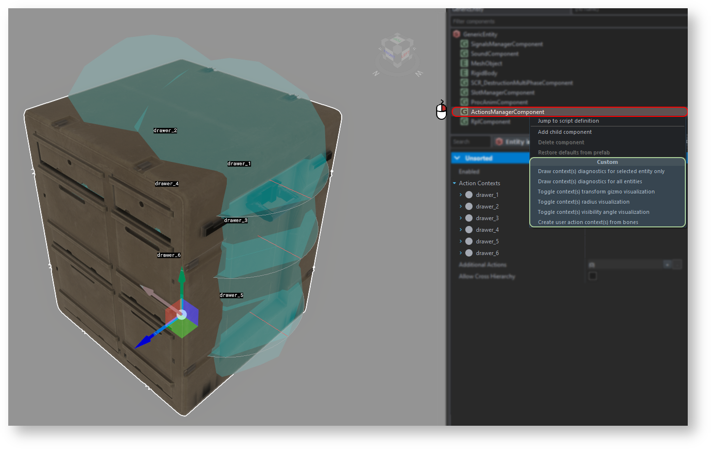
It's also worth to mention that this context menu has few other options, which are quite useful for setting up & debugging of context actions. Below you can see in action transform gizmos (activated via Toggle context(s) transform gizmo visualization ) and radius visualization (activated via Toggle context(s) radius visualization option). Toggle context(s) visibility angle visualization is also quite handy in setting non Omnidirectional actions.
Position of the action context can be further tweaked by changing Offset values in Position object.
Adding additional actions
Additional actions are actions, which are scripted. Some of the actions like get in, switch seat or opening of doors are handled by respective components like DoorComponent or SCR_BaseCompartmentComponent. Other more specific actions, which don't necessarily need a whole component to be handled, are handled via Additional Actions array. In vanilla game, flushing toilet or opening hatches in BTR-70 are handled via this kind of actions and drawer open/close action is also a good candidate to use this method.
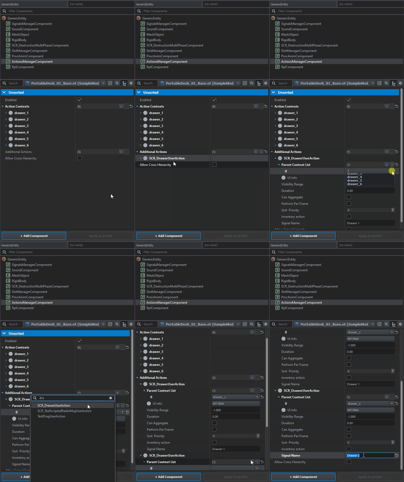
New additional actions can be added to the asset by clicking on plus icon to the right of Additional Actions property inside ActionsManagerComponent. Once that plus sign is clicked, a new menu pops up asking for a type of action which should be added to the asset. In this case SCR_DrawerUserAction should be selected from the list.
After adding first SCR_DrawerUserAction element to the array', there are few things that need to be adjusted over there. First task will be configuring Parent Context List parameter. This array contain list of contexts where this action will be visible. It is possible to use multiple contexts for such action but in this case, only single context - previously created drawer_1 -' should be present in Parent Context List array.
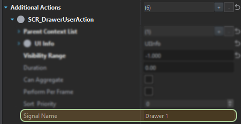
Next thing will be defining of Signal Name parameter. This is custom property which was added by SCR_DrawerUserAction and, as it was mentioned before, it should contain name of the signal defined in Input node of Procedural Animation Editor Signal (.siga file). In this case it will be Drawer 1
If all steps were properly followed, then it should be already possible to test it in-game and verify if the user action is visible & usable. If action is not visible, verify if bone used as Pivot ID is correctly rotated and that radius of action is correct.
Adding sounds
Creating new audio project
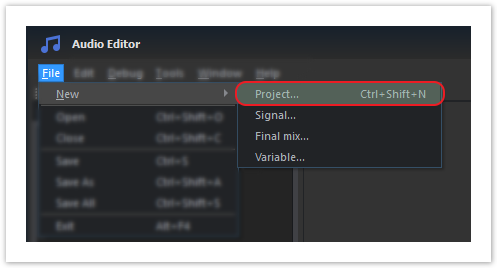
New audio project can be created quite easily inside Audio Editor. To do so, open Audio Editor and either select from File → New → Project... option or use Ctrl + ⇧ Shift + N shortcut.
Setting nodes in audio project
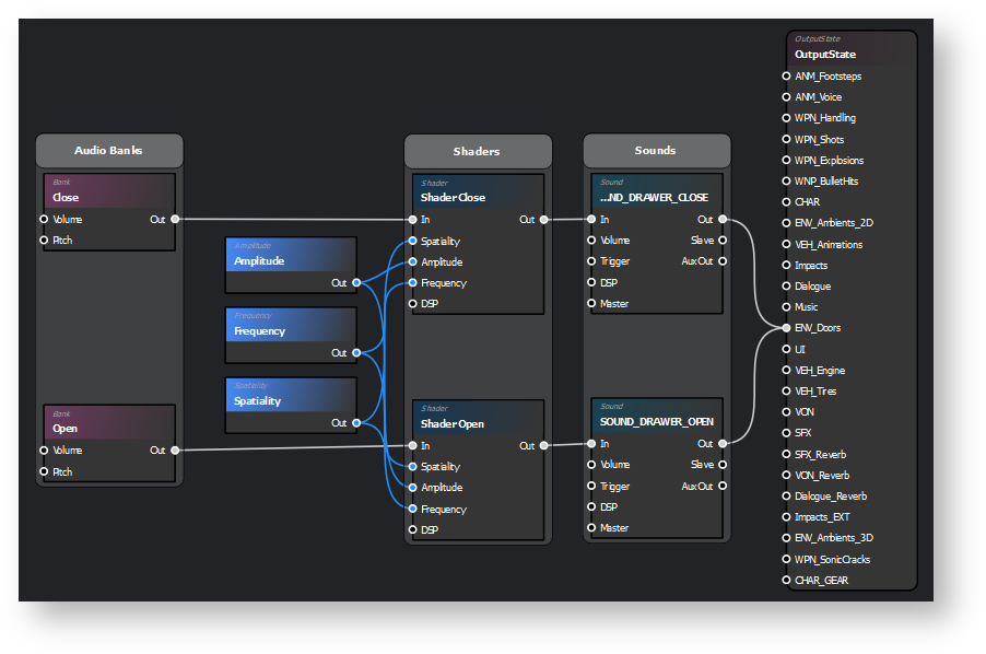
For drawer open/close action following things will be required in audio project:
- 2 BankLocal nodes (aka Bank node) - one for opening and another for closing of drawer
- 2 Shader nodes - separate for opening and drawer. Applies panning and attenuation based on the spatial relation between the in-game listener and emitter
- 2 Sound nodes - same as above. The root node of a signal chain. Must be present in every chain in order for sound to be playable. Name of the Sound node can be later to trigger Sound Event via scripts
- Amplitude node - controls amplitude attenuation that is applied by the Shader - shared with both Shader nodes
- Frequency node - controls frequency attenuation that is applied by the Shader - shared with both Shader nodes
- Spatiality node - controls spatiality that is applied by the Shader - shared with both Shader nodes
- OutputState node (aka Mixer or FinalMix.afm) - This node serves as a way to group sounds based on type so that they can be processed as a unit before being sent to the final output(s). As with the Signal node, this node contains some internal logic that defines how each sound group is processed. This internal logic can be edited by double-clicking on the node.
Adding audio banks
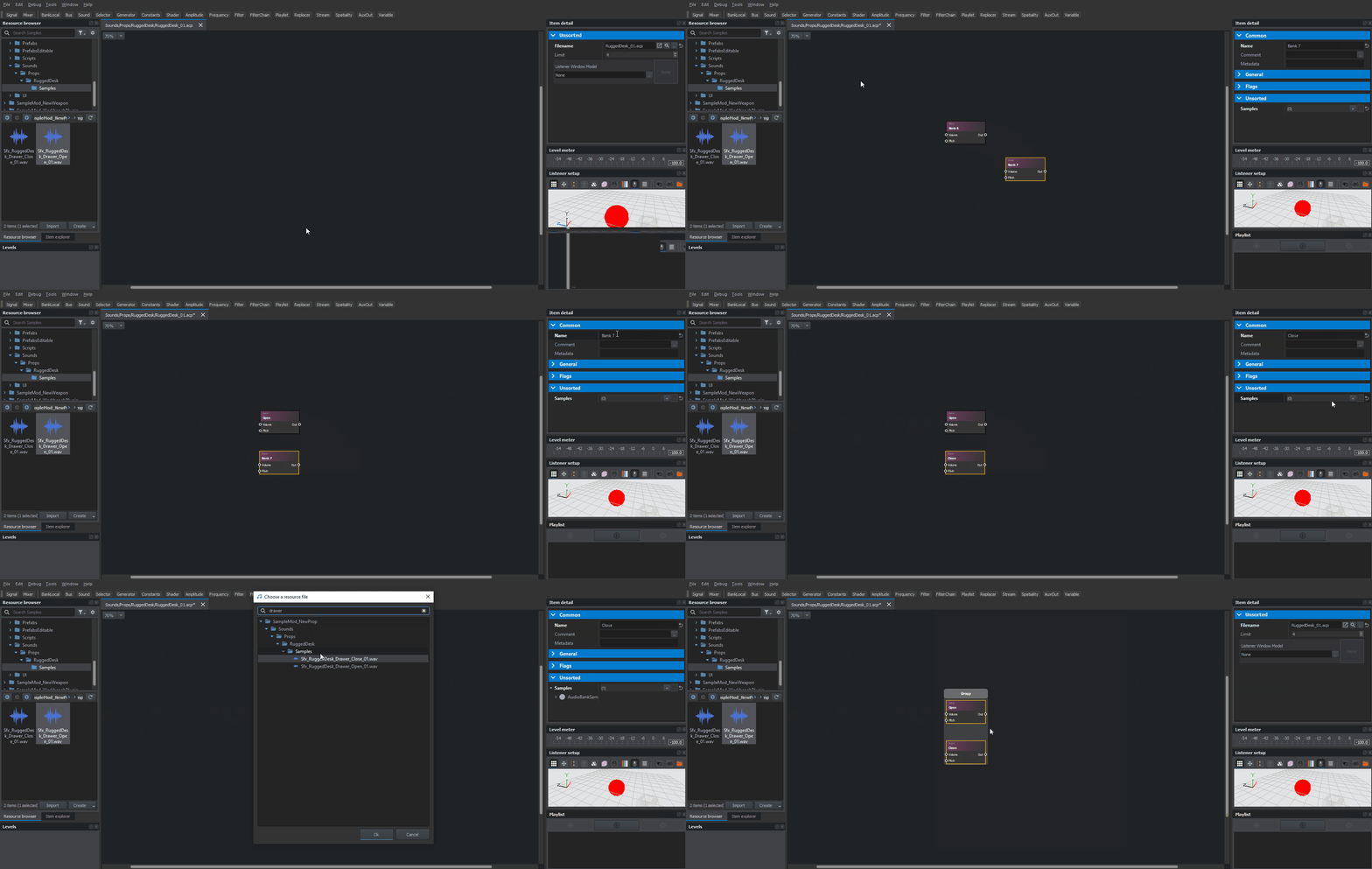
Starting configuration of audio project with creation of audio banks, new Bank nodes can be easily added by following below steps:
- Click on BankLocal button in the upper section of the editor
- Click on that new Bank node and navigate to Unsorted section in Item Detail window
- Fill in Samples array with audio files (start with Sfx_RuggedDesk_Drawer_Open_01.wav) that should be played when this audio bank is used. This can be done in two ways:
- By drag and dropping registered audio file in wav format on Bank node
- By adding new element to Samples array via plus button and then assigning wav file in Filename field
This should be enough to have it in working state. Additionally, following steps can be performed to make it more pleasant to look at:
- Rename Bank node to f.e. "Open" by changing Name parameter in Item Detail window
- Reposition Bank node to make space for another Bank node
After that, above steps can be repeated to create Close Bank node, which would contain Sfx_RuggedDesk_Drawer_Close_01.wav sample. With two bank nodes in place, it is also possible to already start process of beautification of the audio project by aligning and then grouping those nodes in Audio Banks group.
Adding shaders
Process of adding new shaders to audio project is quite similar, if not even simpler, to explained above procedure of adding audio banks.
In principle, those two steps have to be done for both Close and Open variants:
- Click on Shader button in top section of the main window
- Connect Out port on Bank node with In port on Shader node
Once again, it is also recommended to change names of the nodes and then group them improve readability of the audio project.
Adding special nodes
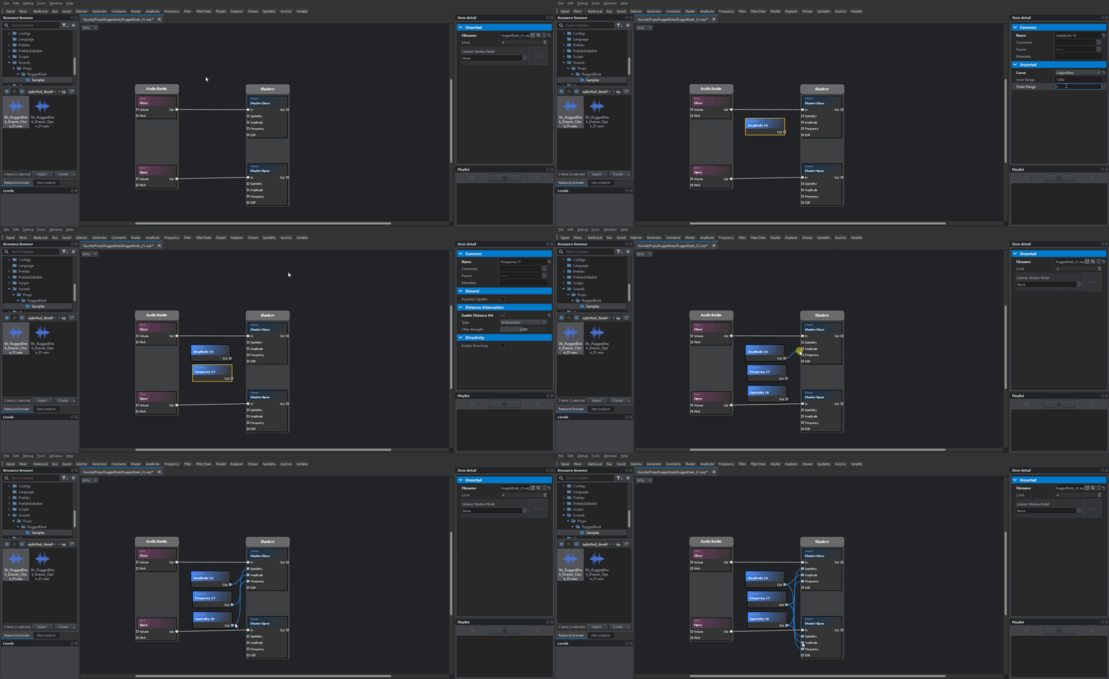
Next in audio project configuration will be adding of Amplitude, Frequency & Spatiality nodes to the working file. Adding of those nodes should be at this point quite straightforward so in this chapter we will focus more on configuration of new nodes.
Beginning with Amplitude node, here are few things that has be done in order to have it working correctly:
- In Item Detail window, change Curve parameter from None to Logarithm. This action will enable attenuation of the sound or in other words, sound will be more silent the further away you are from the sound source.
- After changing Curve parameter to Logarithm, two new parameters should appear:
- Inner Range - this parameter define distance in meters below no attenuation is applied. By default it is set to 1 and for this asset we can leave it as it is
- Outer Range - this parameter define distance in meters beyond sound is muted. For such small drawer as this, 5 meters would be a sensible number
- After changing Curve parameter to Logarithm, two new parameters should appear:
- Amplitude Out port should be connected to Amplitude port on both Close & Open shaders.
Second on the list is Frequency node, which also affects attenuation of the sound & similar to Amplitude node, following things have to be adjusted on that node
- In Item Detail window, enable Enable Distance Att parameter
- Default values should be fine for this rugged desk - for more information see Audio Editor nodes documentation
- Frequency Out port should be connected to Frequency port on both Close & Open shaders.
Last but not least it is time to configure Spatiality node, which controls 3D sound perception.
- In Item Detail window, change Spatial Factor parameter to 1.0 - this will enable 3D like perception of the sound.
- Spatiality Out port should be connected to Spatiality port on both Close & Open shaders.
Adding sound nodes
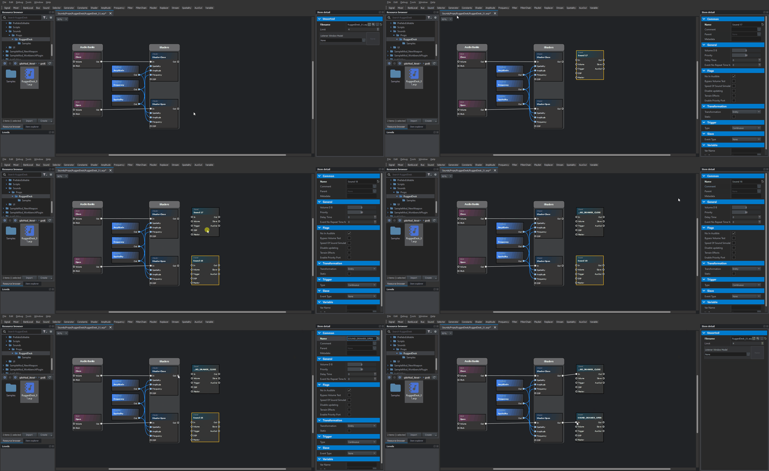
With shaders being properly configured, it is time to move to Sound nodes. In this case, name of the Sound node is important, since it will be later used in script to trigger playing of the sound event. Sound nodes can be added by clicking on Sound button in top section of the main window. Both close and open action need a separate Sound node, so two Sound nodes are necessary.
Once both nodes are present in work board, change their name to SOUND_DRAWER_CLOSE and SOUND_DRAWER_OPEN and then connect it to respective shaders.
Sound nodes have quite a lot of parameters which can be tweaked so at later stage, when whole asset is configured, it is recommended to play with parameters that are available over there.
Adding final mix
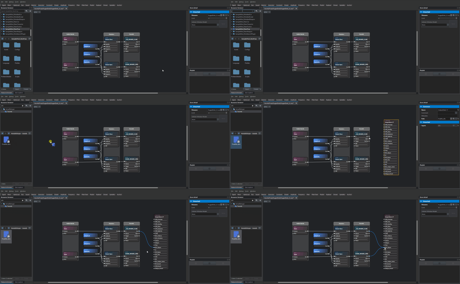
Final step will be adding of FinalMix.afm (also known as Mixer) to the audio project and then connecting outputs of Sound nodes to ENV_Objects port on OutputState node.
Result
In the end, audio project should look somewhat similar to the picture below. Since Procedural Animation Editor & Audio Editor are sharing a lot of code, it is also possible to align & group nodes here too.
It is also possible to check playback of the sounds inside Audio Editor - without switching to play mode - by selecting node and then hitting space button. Example of using sound debug can be found on Weapon Modding tutorial page.
Applying sound to prefab
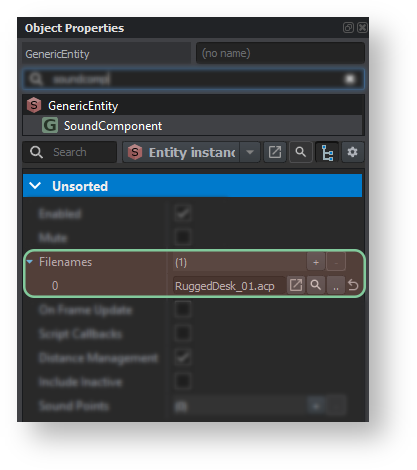
In order to apply sounds to prefab, first step towards would be adding of SoundComponent to it. As described before, this can be achieved by using + Add Component button and selecting SoundComponent from list.
Once that component is present and selected, it is possible to add new element to Filenames array. Since in this tutorial only single .acp file was created, one element in this array should be enough.
After new element in array is present, it is possible to fill that property either by drag and dropping audio project file on that resource field or by clicking on button with two dots and the selecting Rugged Desk .acp file.
Playing sound in script
First step towards triggering a sound from the script will be fetching of SoundComponent in SCR_DrawerUserAction script. Similar to SignalManagerComponent, this can done by using FindComponent method.
Next, at the bottom of PerformAction method, code for triggering sounds can be added. This is done by calling SoundEvent method and passing name of the Sound node, which was previously defined in audio project, as a parameter.
Once those changes are saved and compiled, this desk should be already in state where closing and opening of drawers plays some sounds! Below you can find full code in case you had some troubles with implementing those extra bits of code
Full code
Editor integration
Generating placeable entity
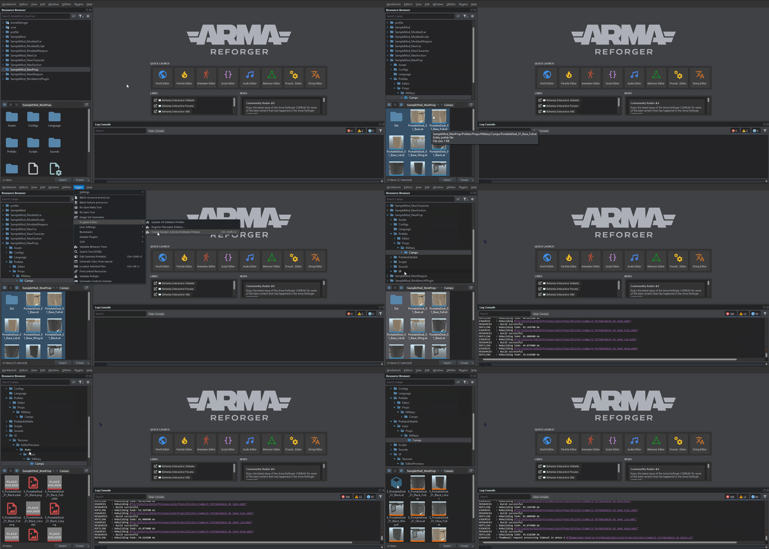
Once the configuration of the prefab is done, it is possible to use one of the editor plugins to prepare Editable Entities. This can be done by using Create/Update Selected Editable Prefabs plugin, which will create new, editable prefabs for assets which usually are not replicated (like props) and don't have one of the Editable Components attached to it.
Usage of that plugin is quite well explained on Game Master Existing Prefab Configuration page and therefore some of the details are skipped here. In case of that set of rugged desk props following steps were performed:
- In Resource Browser (main one, it doesn't work with Resource Browser 2!) attached to Resource Manager, all prefabs in PrefabsEditable → Military → Camps folder were selected. Assets with _base,_Base,_dst,_Dst or_DST suffix are automatically omitted by the plugin so they can be also selected without any issues - this behavior can be tweaked in EditablePrefabsConfig.conf.
- From Plugins→ Editor menu Create/Update Selected Editable Prefabs plugin was selected. Alternatively Ctrl + ⇧ Shift + U shortcut can be used
After that, new prefabs should be automatically generated. Those new editable prefabs created by the plugin are stored in Auto folder of filesystem (aka addon/mod) they belong to. Over there, new inherited prefabs with E_ prefix are present, which are inheriting from original, non editable prefabs and they are mimicking file structure of the original prefab. In this case, it means that all editable prefabs should be located in PrefabsEditable → Auto → Military → Camps folder.
Additionally, plugin also prepares placeholder preview images for all assets - without it, it is impossible to go through next step which is generation of proper preview images.
Generating preview images
New, proper preview images can be created using special world located within Arma Reforger data (link) . Instructions about usage of that special world can be found on Game Master: Image Generation Tutorial and here you can find a short instruction on how it was done for Sample New Prop addon:
- Load Eden_AssetImages.ent
- Select SCR_EditorImageGeneratorEntity from Hierarchy window
- Adjust viewport to 400x300
- In diagnostic menu, set Game > Compressed format in WB to true
- Select prefabs in Resource Browser attached to World Editor which should be subject of preview image generation. In this case all prefabs in PrefabsEditable → Auto → Military → Camps folder were selected
- Switch to Play mode
If editable prefabs were correctly generated in previous step, then new pictures should be ready to use. If not, check Console Log for hints about what went wrong.
Changing display name
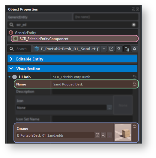
Display name of the prefab can be changed in prefabs located in PrefabsEditable folder inside Auto subfolder which was described in paragraph about generating placeable entities.
Once those editable prefabs are located and present in World Editor (either by placing them or using Edit prefab button), it is time to change their configuration. Bunch of editor related configuration is located in SCR_EditableEntityComponent and among parameters that you can change there you can find Name parameter in Visualization section of that component.
Over here, change Name parameter so it reflects desired display name of that asset in Entity Browser - in this case Sand Rugged Desk was picked, and it was made inline with Arma_Reforger:Editor_Entity_Naming_Conventions
Setting up localization table
After changing the strings in the prefab, it is possible to use localization plugin to add string to localization table. It is also worth to note, that in some case it might be faster to first localize placeholder strings and then change those strings inside String Editor - in any case, both workflows have their advantages and its matter of preference which one to use.
In this example, first method was used - adjusting display names in prefab and then putting those strings to localization table (.st) via Localize Selected Assets plugin. Before that, it is necessary to create localization table and runtime variant of it and the register those elements in game project. Whole process is described in detail on Mod Localisation so here is short version of that procedure:
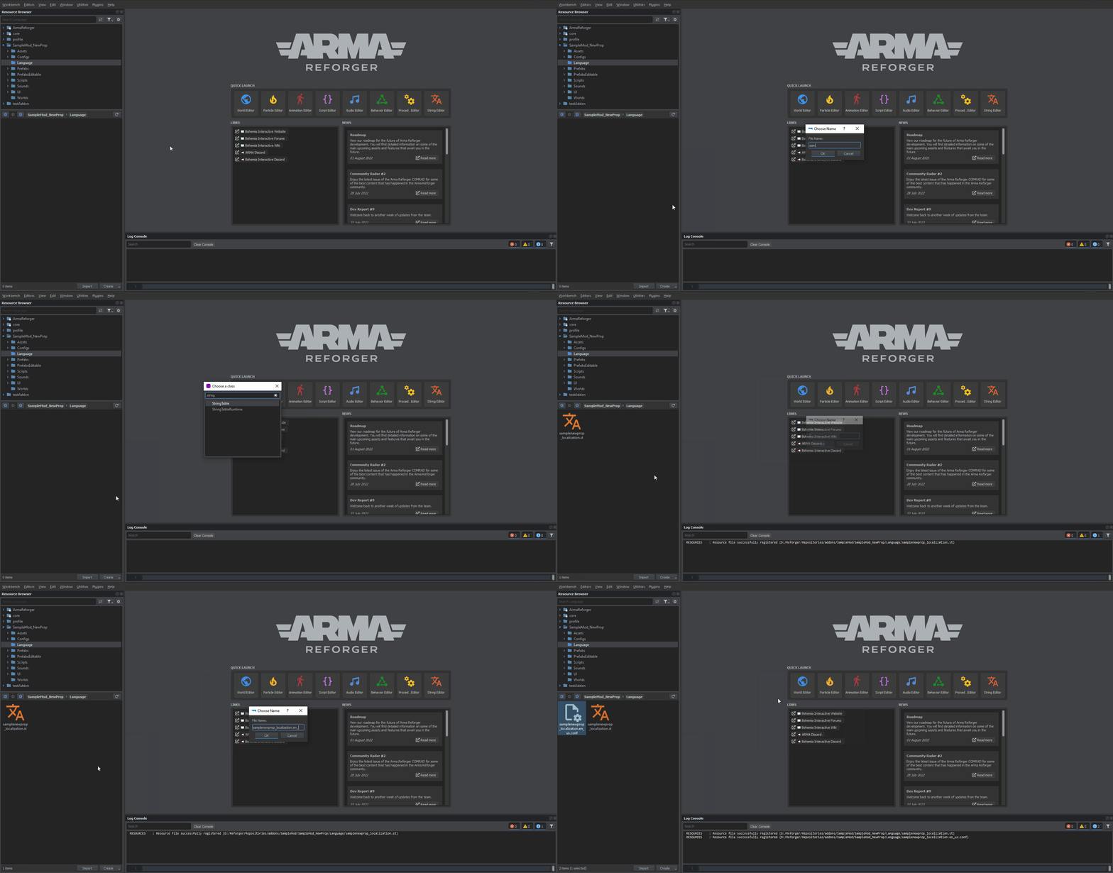
- Create "Language" folder in the root addon file system
- Inside of that folder, following files have to be created:
- GUI string table - this is main file which is used by String Editor. It is important to assign to it unique name so it doesn't clash with other mods - in this case file was called samplenewprop_localization.st
- After samplenewprop_localization.st was created, click on it with
 and select Open File in New Tab option from Context Menu and set parameters to following values:
- Target Prefix: Target_
- Item Class Name: CustomStringTableItem
- After samplenewprop_localization.st was created, click on it with
- StringTableRuntime - version of localization table used by the game - it is stripped from all String Editor related content. Each language needs separate config file. In this tutorial, samplenewprop_localization.en_us.conf was created
- GUI string table - this is main file which is used by String Editor. It is important to assign to it unique name so it doesn't clash with other mods - in this case file was called samplenewprop_localization.st
Once files are created, it is time to plug them into game project:
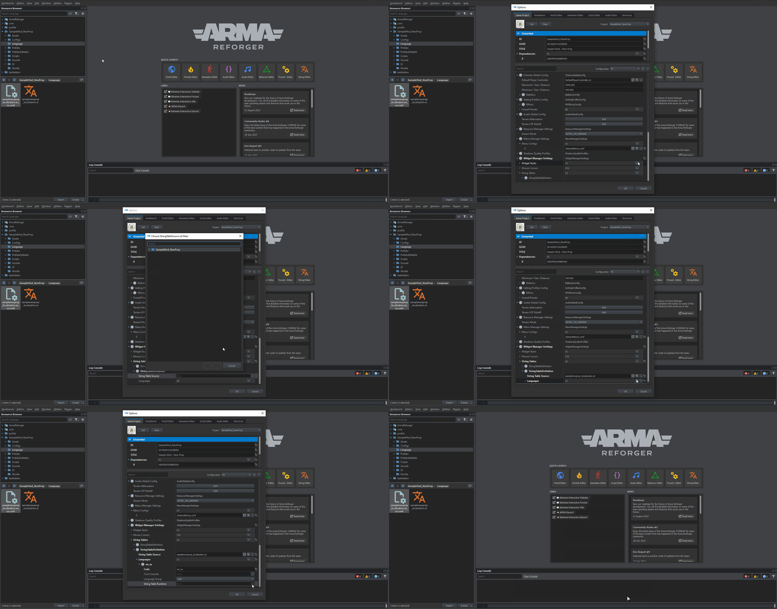
- Open Workbench options by clicking on Options from Workbench top menu.
- Navigate to Widget Manager Settings → String Tables
- Added new StringTableDefinition
- Assign samplenewprop_localization.st to String Table Source property
- Add new element to Languages array
- Change Code property to en_us
- Assign samplenewprop_localization.en_us.conf to String Table Runtime property
- Save changes by clicking on OK button
Adding strings to localization table
With string table in place, it is possible to actually fill it with data. This can be done by following below steps (see Mod Localisation for more details):
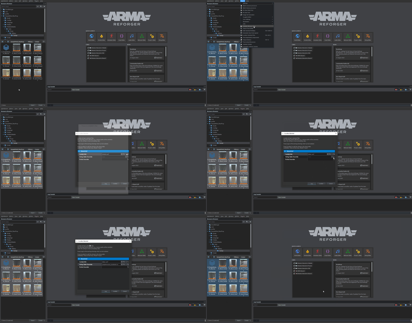
- Select all prefabs inside PrefabsEditable → Auto → Military → Camps folder in Resource Browser (it can be either Resource Browser attached to Resource Manager or World Editor)
- Click on Localize Selected Assets in Plugins tab or use Ctrl + ⇧ Shift + L shortcut
- In window that appeard make following adjustment:
- Change Config Path config and use
- Assign samplenewprop_localization.st in String Table Override property
- Type SampleMod- in Prefix Override property
- Click on Localize button
Plugin now should open samplenewprop_localization.st in String Editor and fill all the detected strings. If file is empty, then make sure that String Table Override property is correctly assigned and check Console Log for errors or warnings.
Adjusting labels
Entity labels are used by in-game Editor Entity Browser to filter content. By default, some of those labels are automatically assigned by Create/Update Selected Editable Prefabs plugin base on their type (is it GenericEntity or Vehicle class?), folder in which they are located (Prefabs in Prefabs/Military folder will get Theme_Military label), parameters in their prefabs (Mass in RigidBody, size of the group by counting elements in Unit Prefab Slots, etc), size of bounding box and so on. Most of those rules can be checked by opening EditablePrefabsConfig.conf. It is also possible to add some custom rules as it was for instance described in the Faction creation guide.
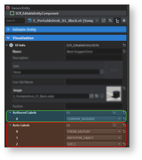
Beside that, it is also possible to manually add extra labels or even custom ones by changing content of Authored Labels array in SCR_EditableEntityComponent . In case of that prop, it is recommended to add CONTENT_MODDED label to Authored Labels array (Auto Labels array shouldn't be touched by the user since content of that array might get overridden by editor plugin!) for each asset prefab in PrefabsEditable → Auto → Military → Camps folder. This can be done by clicking on button with plus sign on the right side of the Authored Labels property and then select from that new element in array CONTENT_MODDED label from drop down menu.
Registering asset
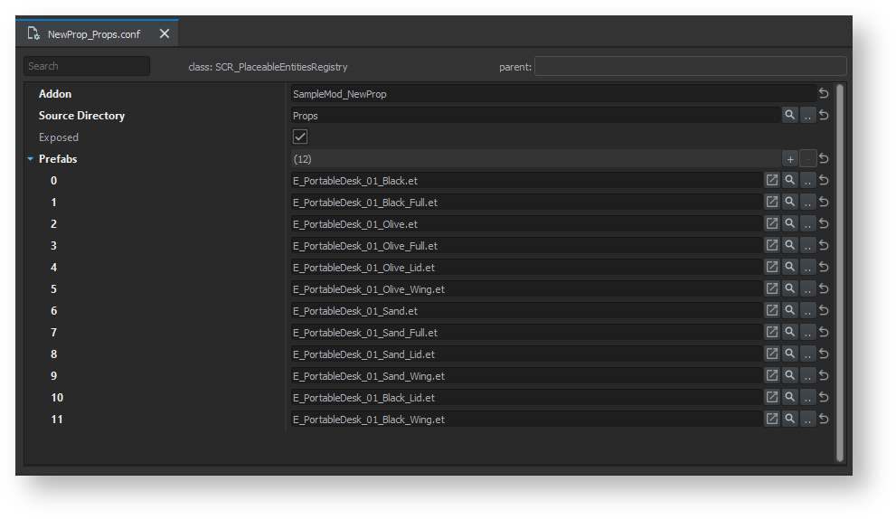
The final step in editor integration is adding editable props to register of placeable assets. Whole process is described in detail on Asset Browser Mod Integration page so here is simplified list of steps that had to be done:
- Create new SCR_PlaceableEntitiesRegistry register in SampleMod_NewProp\Configs\Editor\PlaceableEntities called NewProp_Props.conf
- Override in addon EditorModeEdit.et
- Open EditorModeEdit.et and in SCR_PlacingEditorComponent, add new entry to Registries array by i.e. drag and dropping NewProp_Props.conf
- Save changes in EditorModeEdit.et
- OpenNewProp_Props.conf, select all prefabs in PrefabsEditable → Auto → Military → Camps inside Resource Browser attached to Resource Manager and then drop that selection onto Prefabs array inside of that config
- Furthermore, you can also change Addon & Source Directory property so plugin can in future semi-automatically fill or update that Prefabs array
After all those steps, assets should be available in in-game Entity Browser!
Testing result
In Workbench, new prop can be tested either by launching Game Master scenario and then placing new assets through Asset Browser or by simply creating a new sub-world in World Editor and then placing asset in game
Testing in Game Master
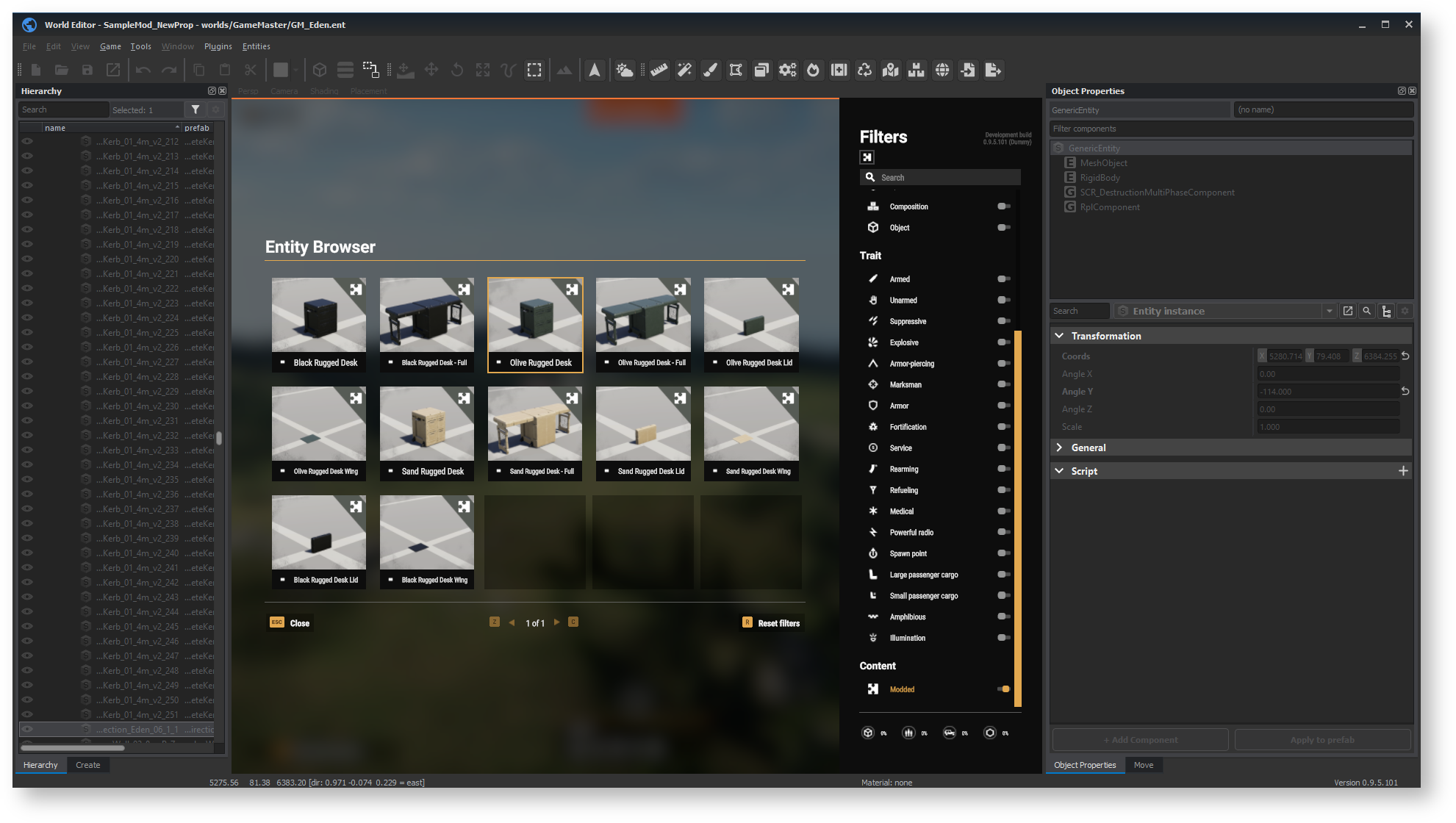
To test new prop in Game Master, load GM_Eden.ent world in World Editor and once it's ready, switch to Play mode by either pressing on green arrow or via F5 shortcut (furthermore, that option is also available in Game tab). This should initiate loading of scenario and once it's completed, regular Game Master interface should be present.
Now, by bringing up Entity Browser either by pressing Tab or by clicking on Place entities button in bottom right section of the interface
Testing in new world
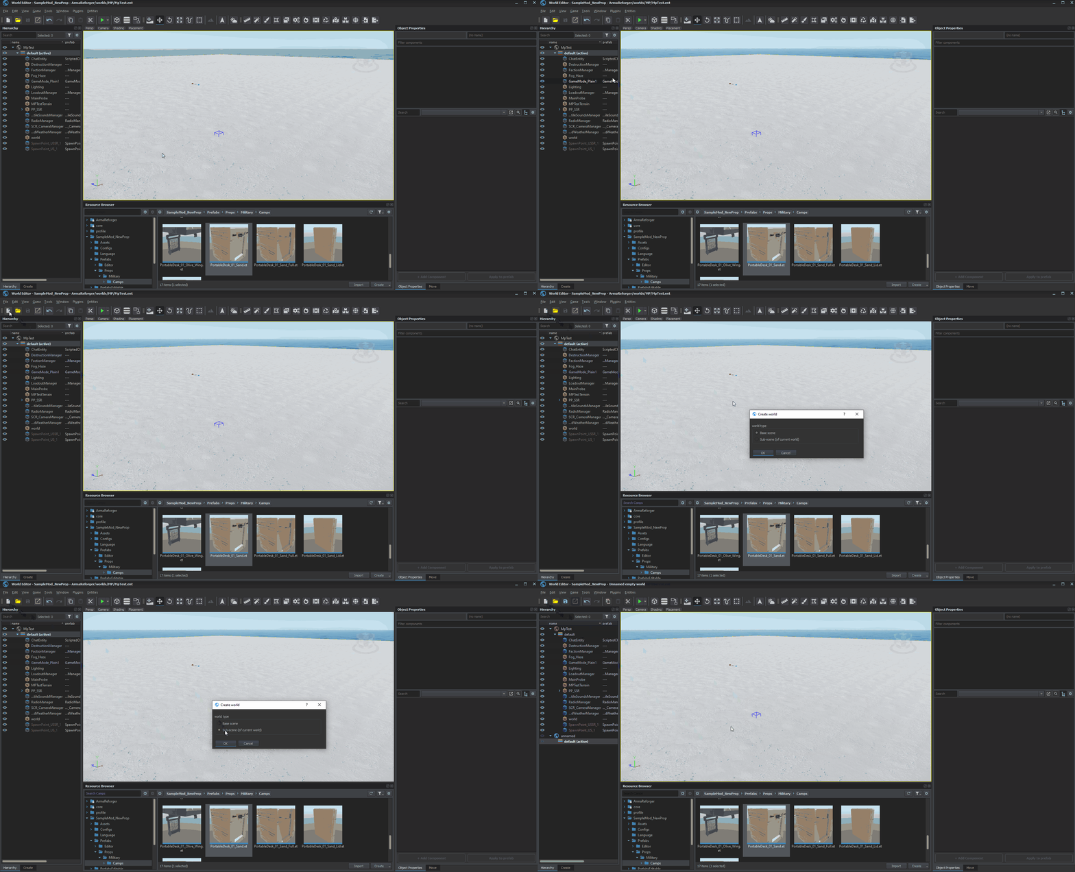
Simplest & fastest way to do it might be loading MpTest world and then creating a new subworld of it. To do so, follow this instruction:
- Click on File → New World (Ctrl + N shortcut) or on New World icon in the toolbar
- Select Sub-scene (of current world) option and confirm it with OK button
- Save current world by selecting File → Save World option (Ctrl + S shortcut) and save it somewhere inside your addon
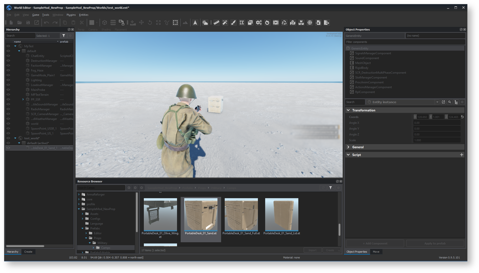
After that, you can place prop prefab - i.e. PortableDesk_01_Sand.et - into the world and switch to Play mode. Once in play mode, you should be able to interact with the prop!
